
Servo motor works on the principal of Pulse Width Modulation (PWM) and its angle of rotation is controlled by the duration of the pulse applied to its control pin. Here in this tutorial we will control a servo motor with ATtiny13 microcontroller using PWM technique. So before going any further we will first learn about PWM, Servo Motor and how to program ATtiny13 with Arduino Board.
Pulse Width Modulation (PWM)
Pulse Width Modulation (PWM) is defined as a method for generating an analog signal using a digital source. A PWM signal consists of two main components- duty cycle and frequency. These components define its behavior. Duty cycle describes the amount of time the signal is in a high state. It is denoted as a percentage of the total time it takes to complete one cycle.
Duty Cycle =Turn ON time/ (Turn ON time + Turn OFF time)
The frequency defines how fast the PWM completes a cycle and how fast the signal switches between high and low states. A frequency of 100Hz means 100 cycles per second. By switching a digital signal ON and OFF at a fast rate and with a certain duty cycle, the output will appear like a constant voltage analog signal. One of the powerful benefits of PWM is that the power loss is very minimal.
PWM signals are used for a variety of control applications. The main purpose of the PWM signal is to control the power that is supplied to various electrical devices, especially to inertial loads such as AC/DC motors. It can also be used to control pumps, valves, hydraulics, and other mechanical parts. The frequency of the PWM signal depends upon the application and the response time of the device that is being powered.
Controlling Servo Motors using PWM signals
A servo motor consists of three wires, out of which two are used for power supply (positive and negative) and one control wire is used for the signal that is to be sent from the microcontroller. A servo motor is basically made up of a DC motor which is controlled by a potentiometer and some gears. The high speed force of a DC motor is converted into torque by the gears. In a DC motor force is less and speed is high where as in a servo motor, force is high and speed is less. The potentiometer is connected to the output shaft of the servo motor to calculate the angle and to stop the DC motor on the required angle. To learn more about Servos follow the detailed article on Servo Motor.
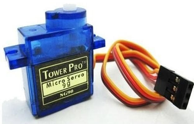
Servo motor is controlled by pulse width modulation (PWM) or sending an electrical pulse of variable width, through the control wire. There will be a repetition rate, a minimum pulse, and a maximum pulse. A servo motor can turn 90o in either direction from its neutral position for a total movement of 180o. The motor’s neutral position is where the servo has the same amount of potential rotation in both the clockwise and counter-clockwise direction. The PWM signal sent to the motor determines the position of the shaft. The rotor will turn to the desired position based on the duration of the pulse sent through the control wire. The servo motor expects a pulse every 20 milliseconds (ms) and the length of the pulse determines how far the motor will turn.
A servo motor can be rotated from 0 to 180 degree. When a 1.5ms pulse is given to the control wire the motor will turn to the 90o position. When a pulse shorter than 1.5ms is given, the motor will move in the counter-clockwise direction towards the 0o position. If a pulse longer than 1.5ms is given, then the motor will turn in a clockwise direction towards the 180o position.
All servo motors work directly with +5V supply, but we have to be careful on the amount of current the motor would consume. If we are using more than two servo motors a proper servo shield should be designed.
Before Connecting Servo to Attiny13, you can test your servo with the help of this Servo Motor Tester Circuit. Here we have interfaced servo motor with many microcontrollers:
- Interfacing Servo Motor with ARM7-LPC2148
- Interfacing Servo Motor with MSP430G2
- Controlling Multiple Servo Motors with Arduino
- Interfacing Servo Motor with PIC Microcontroller using MPLAB and XC8
- Servo Motor Control with Raspberry Pi
- Servo Motor Control with Arduino Due
- Interfacing Servo Motor with AVR Microcontroller Atmega16
Programming ATtiny13 using Arduino
Attiny13 can be programmed using Arduino Uno or any other Arduino board. Connect Attiny13 to Arduino Uno as shown in the figure below.
- Arduino 5V – ATtiny13 pin 8
- Arduino GND – ATtiny13 pin 4
- Arduino pin 13 – ATtiny13 pin 7
- Arduino pin 12 – ATtiny13 pin 6
- Arduino pin 11 – ATtiny13 pin 5
- Arduino pin 10 – ATtiny13 pin 1

Arduino is set as a programmer to program ATtiny13. This is done by uploading ArduinoISP sketch to Arduino. This Arduino sketch is available inside the examples in Arduino IDE. Open the Arduino IDE and go to Files > Examples > ArduinoISP.

Now the program for ArduinoISP will pop up. Upload the program to the Arduino Uno.

Arduino Uno is now ready to program Attiny13. But we have to set up the Attiny by installing its core files. To do this go to File>>Preferences in Arduino IDE

Then a new window will pop-up. And in the “Additional Board Manager URL’s” add the below link and click “OK”.
“https://raw.githubusercontent.com/sleemanj/optiboot/master/dists/package_gogo_diy_attiny_index.json”

Now in your Arduino IDE go to Tools>>Board>>Boards Manager

Then another window will pop-up where in search box type ‘Attiny’ then you will get “DIY ATtiny” then click on ‘install’ button (I already installed it, that is why the install button in gray colour)

To start programming ATtiny 13, we must burn Bootloader to it. For that, go to Tools > Board > ATtiny13.

Now go to Tools > Processor version and check whether the correct version of ATtiny is selected. Select either ATtiny13 or ATtiny13a depending on your chip.
Then click Burn bootloader button at the bottom of the Tools menu.

After burning the bootloader, ATtiny is now ready to be programmed. Now you can upload your program.
Components Required
- ATtiny13 Microcontroller
- Servo motor
- Potentiometer
- +5V battery
- Arduino IDE
- Connecting wires
Circuit Diagram and Working
Circuit diagram to control a servo motor using pot with ATtiny13 is given below.

Below are the connections
- Connect the servo motor control pin to pin 5 of ATtiny13
- Connect ground of servo motor to pin 4 of ATtiny13
- Connect VCC of servo motor to pin 8 of ATtiny13
- Connect middle pin of potentiometer to pin 7 of ATtiny13
- Connect the first and third pins of potentiometer to the VCC and GND.
- Connect the positive of +5V battery to the pin 8 of ATtiny13
- Connect the negative of +5V battery to the pin 4 of ATtiny13

A potentiometer is connected to the pin 7 (PB2) of the ATtiny13 and the control wire of the servo motor is connected to pin 5 (PB0).
Here the potentiometer value is read and it is converted to a value between 0 and 180. Then this angle value is converted to microseconds and a pulse is given to the control pin of servo motor with the calculated microseconds delay. Now the servo motor will turn according to the value of the potentiometer as demonstrated in the video given below.
Complete Project Code
#define F_CPU 9600000
int servo = PB0;  //connect servo to PB0
long angle;
int pwm;
#include <avr/io.h>
void adc_setup (void)
{
    // Set the ADC input to PB2/ADC1
  ADMUX |= (1 << MUX0);
  ADMUX |= (1 << ADLAR);
  // Set the prescaler to clock/128 & enable ADC
  // At 9.6 MHz this is 75 kHz.
  ADCSRA |= (1 << ADPS1) | (1 << ADPS0) | (1 << ADEN);
}
int adc_read (void)
{
  // Start the conversion
  ADCSRA |= (1 << ADSC);
  // Wait for it to finish
  while (ADCSRA & (1 << ADSC));
  return ADCH; // return the value
}
void setup()
{
  pinMode(servo, OUTPUT);  // set servo as output pin
}
void loop ()
{
  long a;
  adc_setup();
  a = adc_read();  // read the potentiometer value
  angle = (a * 3) / 2; // convert the reading to angle between 0 and 180.
  servoPulse(servo, angle);  // call the servoPulse function.
}
void servoPulse (int servo, int angle)
{
  pwm = (angle * 11) + 500;    // Convert angle to microseconds
  digitalWrite(servo, HIGH);
  delayMicroseconds(pwm);
  digitalWrite(servo, LOW);
  delay(50);                   // Refresh cycle of servo
}

I'm a newbie just trying to make sense of stuff. I liked your example.
In your example,
// Set the prescaler to clock/128 & enable ADC
you set the prescalers as
ADCSRA |= (1 << ADPS1) | (1 << ADPS0) | (1 << ADEN);
should that have been
ADCSRA |= (1 << ADPS2) | (1 << ADPS1) | (1 << ADPS0) | (1 << ADEN);