

Servo motors are basically rotary actuators that enable precise control of angular position, acceleration and velocity in various embedded system applications. Commonly having a rotation limit of 90o to 180o, servo motors are DC motors equipped with servo mechanism to sense and control angular position. They are used where there is a need for accurate shaft movement or position. These are not proposed for high speed applications but proposed for low speed, medium torque and accurate position application. These motors are mainly used in robotic arm machines, flight controls and control systems. A servo motor is shown in the below image.

Servo motors are available at different shapes and sizes. As shown in figure a servo motor have three wires - RED wire is connected to power, Black wire is connected to ground and YELLOW wire is connected to signal.
A servo motor is a combination of DC motor, position control system and gears. The position of the shaft of the DC motor is adjusted by the control electronics in the servo, based on the duty ratio of the PWM signal the SIGNAL pin. Simply speaking the control electronics adjust shaft position by controlling DC motor. This data regarding position of shaft is sent through the SIGNAL pin. The position data to the control should be sent in the form of PWM signal through the Signal pin of servo motor.
The frequency of PWM (Pulse Width Modulated) signal can vary based on type of servo motor. The important thing here is the DUTY RATIO of the PWM signal. Based on this DUTY RATIO the control electronics adjust the shaft.
As shown in figure below, for the shaft to be moved to 9o clock the TURN ON RATION must be 1/18.ie. 1ms of ON time and 17ms of OFF time in a 18ms signal.
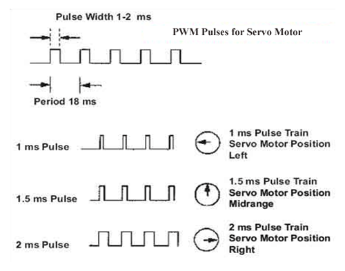
For the shaft to be moved to 12o clock the ON time of signal must be 1.5ms and OFF time should be 16.5ms. This ratio is decoded by control system in servo and it adjusts the position based on it.
Circuit Components
- +9v to +12v power supply
- Servo motor (which needed to be tested)
- 555 Timer IC
- 33KΩ, 10KΩ (2peices), 68KΩ and 220Ω resistors
- 2N2222 transistor
- 100nF capacitor
- Two buttons
Servo Tester Circuit Diagram and Working Explanation

A servo testing circuit is shown in the above schematic diagram. Now as we discussed earlier for the servo shaft to move left all the away. We have to give 1/18 turn on ratio, and for the shaft to rotate all the way to the left we need to give PWM with a duty ratio of 2/18. Now for a 555 astable vibrator shown in below figure, the turn on and turn off times of output square wave are given as,
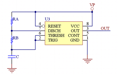
High Level logic time is given as, TH= 0.693*(RA+RB)*C
Low Level logic time is given as, TL= 0.693*RB*C
If you observe the circuit diagram in above figure it will be clear that, we are going to change to change RB to get a different TL and TH. So when button1 is pressed we are going to get a duty ratio less than 1/18, thus when we fed it to servo, it moves all the way to the left. This is shown in figure below.

When the button two is pressed the duty ratio will be 2/18 and so the servo shaft tries to move all the way to the right. This is how we test a servo motor.
Comments
Hi, thank you for you tutorial, helped me a lot ! I just have this problem, both buttons are turning it left, how to turn it right.. ?
how to control servo motor speed.....
You need to use some micro controller (preferably Arduino) and then you can control the speed using PWM concept.
Can teel me how the circuit component works
Like tarnsistor whate its jop in the circuit
Thanks

was the circuit diagram real.........