

This is our 11th tutorial of Learning PIC microcontrollers using MPLAB and XC8. In this tutorial we will learn How to control Servo Motor with PIC Microcontroller. If you have already worked with Servo motors you can skip the first half of this tutorial but if you are new to servo motor itself then continue reading.
Till now, we have covered many basic tutorials like LED blinking with PIC, Timers in PIC, interfacing LCD, interfacing 7-segment, ADC using PIC etc. If you are an absolute beginner, then please visit the complete list of PIC tutorials here and start learning.
In our previous tutorial we learnt how to generate PWM signals using PIC Microcontroller, the signals were generated based on the value read from the potentiometer. If you have understood all programs then, Congratulations you have already coded for a Servo motor also. YES, Servo motors respond to the PWM signals (which we create using timers here) we will learn why and how in this tutorial. We will simulate and build the hardware setup for this project and you can find the detailed Video at the end of this Tutorial.
What is a Servo Motor?
A Servo Motor is a type of actuator (mostly circular) that allows angular control. There are many types of Servo motors available but in this tutorial let us concentrate on the hobby servo motors shown below.
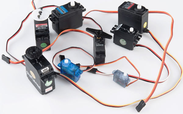
Hobby servos are a popular because they are the inexpensive method of motion control. They provide an off-the-shelf solution for most of the R/C and robotic hobbyist's needs. They also eliminate the need to custom design a control system for each application.
Most of the hobby servo motors have a rotational angel of 0- 180° but you can also get 360° servo motor if you’re interested. This tutorial uses a 0- 180° servo motor. There are two types of Servo motors based on the gear, one is the Plastic Gear Servo Motor and the other is Metal Gear Servo Motor. Metal gear is used in places where the motor is subjected to more wear and tear, but it comes only at a high price.
Servo motors are rated in kg/cm (kilogram per centimetre) most hobby servo motors are rated at 3kg/cm or 6kg/cm or 12kg/cm. This kg/cm tells you how much weight your servo motor can lift at a particular distance. For example: A 6kg/cm Servo motor should be able to lift 6kg if the load is suspended 1cm away from the motors shaft, the greater the distance the lesser the weight carrying capacity. Learn here the Basics of Servo motor.
Interfacing Servo Motors with Microcontrollers:
Interfacing hobby Servo motors with MCU is very easy. Servos have three wires coming out of them. Out of which two will be used for Supply (positive and negative) and one will be used for the signal that is to be sent from the MCU. In this tutorial we will be using a MG995 Metal Gear Servo Motor which is most commonly used for RC cars humanoid bots etc. The picture of MG995 is shown below:
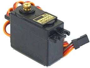

The colour coding of your servo motor might differ hence check for your respective datasheet.
All servo motors work directly with your +5V supply rails but we have to be careful on the amount of current the motor would consume, if you are planning to use more than two servo motors a proper servo shield should be designed. In this tutorial we will simply use one servo motor to show how to program our PIC MCU to control the motor. Check below links for interfacing Servo Motor with other Microcontroller:
- Servo motor interfacing with 8051 microcontroller
- Servo motor control using Arduino
- Raspberry Pi Servo Motor Tutorial
- Servo Motor with AVR Microcontroller
Programming Servo Motor with PICF877A PIC Microcontroller:
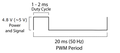
Before we can start programming for the Servo motor we should know what type of signal is to be sent for controlling the Servo motor. We should program the MCU to send PWM signals to the signal wire of the Servo motor. There is a control circuitry inside the servo motor which reads the duty cycle of the PWM signal and positions the servo motors shaft in the respective place as shown in the picture below
Each servo motor operates on a different PWM frequencies (most common frequency is 50HZ which is used in this tutorial) so get the datasheet of your motor to check the on which PWM period your Servo motor works.
The details on the PWM signal for our Tower pro MG995 is shown below.
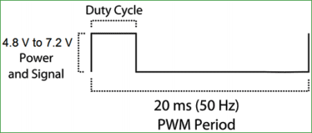
From this we can conclude that our motor works with a PWM Period of 20ms (50Hz). So the frequency of our PWM signal should be set to 50Hz. The frequency of the PWM that we had set in our previous tutorial was 5 KHz, using the same will not help us here.
But, we have a problem here. The PIC16F877A cannot generate low frequency PWM signals using the CCP module. According to the datasheet the lowest possible value that can be set for the PWM frequency is 1.2 KHz. So we have to drop the idea of using CCP module and find a way to make our own PWM signals.
Hence, in this tutorial we will use the timer module to generate the PWM signals with 50Hz frequency and vary their duty cycle to control the angel of the servo motor. If you are new to timers or ADC with PIC please fall back to this tutorial, because I will be skipping most of the stuff since we have already covered them there.
We initialize our Timer module with a prescaler of 32 and make it overflow for every 1us. According to our data sheet the PWM should have a period of 20ms only. So our on time and off time together should be exactly be equal to 20ms.
    OPTION_REG = 0b00000100;  // Timer0 with external freq and 32 as prescaler
    TMR0=251;       // Load the time value for 1us delayValue can be between 0-256 only
    TMR0IE=1;       //Enable timer interrupt bit in PIE1 register
    GIE=1;          //Enable Global Interrupt
    PEIE=1;         //Enable the Peripheral Interrupt
So inside our interrupt routine function, we turn on the pin RB0 for the specified time and turn it off for the reaming time (20ms – on_time). The value of the on time can be specified by using the Potentiometer and ADC module. The interrupt is shown below.
oid interrupt timer_isr()
{
    if(TMR0IF==1) // Timer has overflown
    {
        TMR0 = 252;     /*Load the timer Value, (Note: Timervalue is 101 instaed of 100 as the
                         TImer0 needs two instruction Cycles to start incrementing TMR0 */
        TMR0IF=0;       // Clear timer interrupt flag
        count++;
    }

    if (count >= on_time)
    {
        RB0=1;  // complement the value for blinking the LEDs
    }

    if (count >= (on_time+(200-on_time)))
    {
        RB0=0;
        count=0;
    }
}
Inside our while loop we just read the value of potentiometer by using the ADC module and update the on time of the PWM using the read value.
    while(1)
    {
        pot_value = (ADC_Read(4))*0.039;
        on_time = (170-pot_value);
    }
This way we have created a PWM signal who’s Period is 20ms and has a variable duty cycle which can be set using a Potentiometer. Complete Code has been given below in code section.
Now, let’s verify the output using proteus simulation and proceed to our hardware.
Circuit Diagram:
If you have already come across the PWM tutorial then the schematics of this tutorial will be same except for which we will be adding a servo motor in place of the LED light.

Simulation and Hardware Setup:
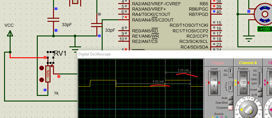
With the help of Proteus simulation we can verify the PWM signal using a oscilloscope and also check the rotating angel of the Servo motor. Few snapshots of the simulation is shown below, where the rotating angel of the servo motor and PWM duty cycle can be noticed to get changed based on the potentiometer. Further check the Full Video, of rotation at different PWM, at the end.
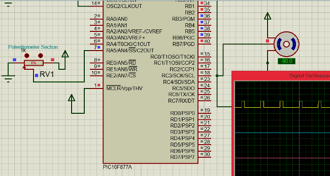
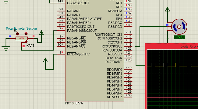
As we can see the servo rotation angel gets changed based on the potentiometer value. Now let us proceed to our hardware setup.
In the hardware setup we have just removed the LED board and added the Servo motor as shown in the schematics above.
The hardware is shown in the picture below:
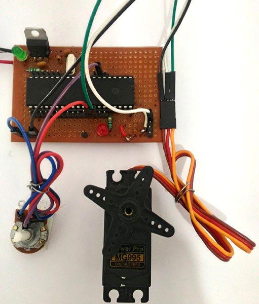
The video below shows how the servo motor reacts to the various positions of the potentiometer.
That is it!! We have interfaced a servo motor with a PIC Microcontroller, now you can use your own creativity and find out applications for this. There are lots of projects out there which use a servo motor.
Complete Project Code
#define _XTAL_FREQ 20000000
// CONFIG
#pragma config FOSC = HS        // Oscillator Selection bits (HS oscillator)
#pragma config WDTE = OFF       // Watchdog Timer Enable bit (WDT disabled)
#pragma config PWRTE = ON       // Power-up Timer Enable bit (PWRT enabled)
#pragma config BOREN = ON       // Brown-out Reset Enable bit (BOR enabled)
#pragma config LVP = OFF        // Low-Voltage (Single-Supply) In-Circuit Serial Programming Enable bit (RB3 is digital I/O, HV on MCLR must be used for programming)
#pragma config CPD = OFF        // Data EEPROM Memory Code Protection bit (Data EEPROM code protection off)
#pragma config WRT = OFF        // Flash Program Memory Write Enable bits (Write protection off; all program memory may be written to by EECON control)
#pragma config CP = OFF         // Flash Program Memory Code Protection bit (Code protection off)
// #pragma config statements should precede project file includes.
// Use project enums instead of #define for ON and OFF.
#include <xc.h>
//TIMER0    8-bit    $$RegValue = 256-((Delay * Fosc)/(Prescalar*4))$$
char value = 0;
int on_time ;//= 150; //On-Time for the PWM signal
int count; //count gets incremented for every timer overlap
int pot_value;

/*********ADC Functions*********/
void ADC_Init()
{
  ADCON0 = 0x41; //ADC Module Turned ON and Clock is selected
  ADCON1 = 0xC0; //All pins as Analog Input
                //With reference voltages VDD and VSS
}
unsigned int ADC_Read(unsigned char channel)
{
  if(channel > 7) //If Invalid channel selected
    return 0;     //Return 0
  ADCON0 &= 0xC5; //Clearing the Channel Selection Bits
  ADCON0 |= channel<<3; //Setting the required Bits
  __delay_ms(2); //Acquisition time to charge hold capacitor
  GO_nDONE = 1; //Initializes A/D Conversion
  while(GO_nDONE); //Wait for A/D Conversion to complete
  return ((ADRESH<<8)+ADRESL); //Returns Result
}
  //*************************************************//

void interrupt timer_isr()
{
    if(TMR0IF==1) // Timer has overflown
    {
        TMR0 = 252;     /*Load the timer Value, (Note: Timervalue is 101 instaed of 100 as the
                         TImer0 needs two instruction Cycles to start incrementing TMR0 */
        TMR0IF=0;       // Clear timer interrupt flag
        count++;
    }

    if (count >= on_time)
    {
        RB0=1;  // complement the value for blinking the LEDs
    }

    if (count >= (on_time+(200-on_time)))
    {
        RB0=0;
        count=0;
    }
}

void main()
{
 /***************I/O PORT Initialization*************/
  TRISB = 0x00; //RB0 used as Servo signal pin
  TRISA = 0xFF; //Analog inputs
 //*************************************************//
 ADC_Init(); //Initializes ADC Module

    OPTION_REG = 0b00000100;  // Timer0 with external freq and 32 as prescaler
    TMR0=251;       // Load the time value for 1us delayValue can be between 0-256 only
    TMR0IE=1;       //Enable timer interrupt bit in PIE1 register
    GIE=1;          //Enable Global Interrupt
    PEIE=1;         //Enable the Peripheral Interrupt
    while(1)
    {
        pot_value = (ADC_Read(4))*0.039;
        on_time = (170-pot_value);
    }
}
Comments
Hi Ana,
I have calibrated the value for TMR0 using the simulation. If you have to make a function for -90, 0 and +90 it will be easy by simply trying that on simulation
Look at for which value if 0n_time the servo reaches -90,0 or 90 and find its corresponding vale. IF you theoretically wanna calculate the value of TMR0 its beyond the scope of this tutorial.
As I can change the pot door, as for example the pot is in the RA5 port, I was wondering if there is any way I can put it on the RA4 port. Has as?
Hi i have converted your code to mikroc but its not working for me, i dont understand were 252 came from and the why are you multiplying 0.039 on the analogue value?
Hi MOAD,
Sorry for confusing you a bit there!!
We have initialized the values 251 in the register TMR0 (TMR0 = 251; ), so at timer over flows for every 1us. The value 1us is not mandatory it can be anywhere above 20ms. Now every time the timer over flows we have to load the same value + 1 into the TMR0 register, that is we have to load 252 inside TMR0 since there will be one additional instruction cycle during reinitializing.
The function ADCRead(4) will give us a value between (0-1024) it is multiplied with 0.039 so that we map them from 0-40. By doing so the variable on_time will vary from 130 to 170. Where 130 will position the servo at 0* and 170 will position it at 180*.
The concept should also work with mikro C, provided you have done the conversion correctly. Let me know what error pops up and I will try to help you out
Hi thanks for your reply,
ok thats very helpful. my other question is how do you know that 130 is the 0 position and 170 is the 180 position (im using a 90 degree servo so it should be fine too right?) i also dont quite understand the bit where you use the 200 value. should not be 170 in this case?
Hi this is still not working, any chance you could help?
Hi again Moad,
They value 200 was obtained form this formulae
Delay = ((256-REG_val)*(Prescal*4))/Fosc
To know more on how timer registers are set and controlled. You might wanna take a look at this tutorial
https://circuitdigest.com/microcontroller-projects/pic-microcontroller-timer-tutorial
Yes, The code is also applicable for a 90* Servo, provided the PWM period is 20ms. Check your datasheet to confirm it. The value 130 and 170 was obtained through experimentation.
As you might know most hobby servos (I am talking about 0-180 servo), cannot rotate all the way down to 0* or all the way up to 180* so based on that you might wanna tweak your values a bit. Using a potentiometer should solve this pblm
could you please explain me the ISR in this case or at least where did you calculate the 50 Hz signal? Thanks in advance!!!!!!
Hi Ana,
To know this you should under stand what kind of input is required for a servo motor to work. Take a look at the following picture.
https://components101.com/sites/default/files/inline-images/how-to-use-…
From the picture we can understand that the PWM signal produced should have a frequency of 50Hz that is the PWM period should be 20ms. Out of which the On-Time can vary from 1ms to 2ms. So when the on-time is 1ms the motor will be in 0° and when 1.5ms the motor will be 90°, similarly when it is 2ms it will be 180°. So, by varying the on-time from 1ms to 2ms the motor can be controlled from 0° to 180°
Hope this helps you!
Ok , I understand that but my question is different what I really want to know is to understand the calculations because I want to generate a PWM duty cycle of 50% of different frequencies I try by myself using the formulae of the other tutorial but It doesnt make sense to me the part of the interruption could you please explain me ? Or at least the value which define the 50Hz thank you
Well its very simple. There are two ways using which you can generate a PWM signal in PIC microcontroller. The most used and conventional way is using the CCP modules. But they cannot produce low range requires like 50Hz so for these we use timers. In this project I have used timers as well and ence will explain the same.
So the formulae for frequency = 1/Time
Formulae for Time = Ton+Toff
So in order to produce a frequency of 50Hz the value of time will be (1/50Hz) which is 20ms. Now you have to make sure that your time that is Ton +Toff is always equal to 20ms. So if your Ton is 5ms then your Toff should be 15ms. Hope you get the Idea Now
Hi, I would like to know how do I add more servo motor thanks
void interrupt timer_isr()
{
if(TMR0IF==1) // Timer has overflown
{
TMR0 = 252; /*Load the timer Value, (Note: Timervalue is 101 instaed of 100 as the
TImer0 needs two instruction Cycles to start incrementing TMR0 */
TMR0IF=0; // Clear timer interrupt flag
count++;
}
if (count >= on_time)
{
RB0=1; // complement the value for blinking the LEDs
}
if (count >= (on_time+(200-on_time)))
{
RB0=0;
count=0;
}
}
Since we are using timers to create PWM you can use any I/O pin attach a motor, in the program RB0 is toggled and hence we are coonecting the signal pin of servo to this pin. Same way you can toggle RB1 and attach the motor to that pin as well
Hi, I tried to pass this program to the pic 18f4520, without success would like to know if popoderia help me
Sir, may I know the overall components and it's diagram for pcb?
Could it be possible to control 4 servo motors with this same idea? If it is could you give me an example or tell me how? Thanks a lot!!
Yes Ana it is possible. But you cannot driver all four motors togather due to current limitations, so you have to use a Driver circuit if you are planning to run 4 servo motors togather
Hi! I need your help. I'm planning on driving 3 servos but you mention that "if you are planning to use more than two servo motors a proper servo shield should be designed". Could you give me some guidance into a servo controller circuit? I have only found this Adafruit 16-channel module, which is quite expensive. I'm sure there must be a simpler way to drive just three.
Any help is much appreciated.
thank you very much for this article since I'm a beginner for this subject this article series is really helpful. at the beginning the servo rotated only 90 degrees with the potentiometer. but I changed the value 170 to 180 and 0.039 to 0.0785 then the servo rotated perfectly 180 degrees. thanks again. :)
Thanks for article. There is a point i dont understand which is if (count >= (on_time+(200-on_time))). on_time+(200-on_time) is always equal 200 which is our period but when count is equal to 200 that is mean 200 times interrupt occured and the total time is 200 * our timer time. is there a mistake?
Thnx it really helps me but i have a query that why 170 and in end of isr ontime +200-ontime
i canot undestande this ontime and 170 and 130 value section
Hi,
Can you make another but the control to be with 2 or 3 buttons ?
And code to be in MPLab. I'm struggling for days and couldn't find a way.
I want to control direction Left-Right from a RX2B chip and put the Pic with a servo. Somehow converting the signal from RX2B wich consists of 2 wires controlling the motor ( polarity will be inversed so the motor turning the other direction ) .
So i want 2 butttons to act as inputs (inputs from RX2B ) and the PIC controlling the servomotor.
I may have issues I need resolved
Thank you so much for the tutorial, <3
So I'm using MPLAB X V6.00 and I have some errors that are occurring quite frequently.
Line 85:22: implicit conversion changes signedness: 'int' to 'unsigned int' [-Wsign-conversion]
Line 93:6: variable has incomplete type 'void'
Line 93:15: expected ';' after top level declarator
main.c:85:22: warning: implicit conversion changes signedness: 'int' to 'unsigned int' [-Wsign-conversion]
return ((ADRESH<<8)+ADRESL); //Returns Result
~~~~~~ ~~~~~~~~~~~^~~~~~~
main.c:93:6: error: variable has incomplete type 'void'
void interrupt timer_isr()
^
main.c:93:15: error: expected ';' after top level declarator
void interrupt timer_isr()
^
;
1 warning and 2 errors generated.
Hey friend, the timer doesnt overflow at 1us, with the value of 251 in TMR0 it overflows at 32us, and i see that you make this happen 200 times to have the tecnically 20ms for the servo required period, but the total period in the code wiht the current values is only 6.4ms, not 20 ms, and that can be seen on simulation.. im wrong at something that dont undertand here?
 with a prescaler of 32 the time per instruction is 6.4us, if TMR0 has 151 it overflows at 5 instructions, letting us with 5*0,0000064 = 32us total overflow time, but it suposed to be 20ms required(?

Hi I will like to make a function without reading the value for a potentiometer instead I want to make a function for -90 and other value but I don't understand why you define TMR0 = 252; and I need to know why because with the formula you gave in the tutorial of timers I could calculate de delay for two different angles. Thanks