

As discussed earlier, Arduino Due is an ARM controller based board designed for electronic engineers and hobbyists. This DUE board can be used for making CNC machines, 3D printers, robotic arms etc. All these projects have a common feature that is Position Control. Any of these projects needs accuracy towards their position. Accurate positions in these machines can be achieved by Servo Motors. In this session we are going to control the position of a Servo Motor with Arduino Due. We have already covered the Servo Motor Interfacing with Arduino Uno and Servo Motor Interfacing with 8051 Microcontroller.
Servo Motors:
Servo Motors are known for their accurate shaft movement or position. These are not proposed for high speed applications. These are proposed for low speed, medium torque and accurate position application. These motors are used in robotic arm machines, flight controls and control systems. Servo motors are also used in some of printers and fax machines.
Servo motors are available at different shapes and sizes. We will be using SG90 Servo Motor in this tutorial. SG90 is a 180 degree servo motor. So with this servo we can position the axis from 0 to 180 degrees.

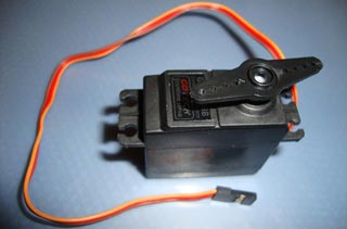
A Servo Motor mainly has three wires, one is for positive voltage, another is for ground and last one is for position setting. The RED wire is connected to power, Brown wire is connected to ground and YELLOW wire (or WHITE) is connected to signal.
A Servo Motor is a combination of DC motor, position control system and gears. In servo, we have a control system which takes the PWM signal from signal pin. It decodes the signal and gets the duty ratio from it. After that it compares the ratio to the predefined positions values. If there is a difference in the values, it adjusts the position of the servo accordingly. So the axis position of the servo motor is based on the duty ratio of the PWM signal to the SIGNAL pin.
The frequency of PWM (Pulse Width Modulated) signal can vary based on type of servo motor. The important thing here is the DUTY RATIO of the PWM signal. Check this for PWM with Arduino Due. However in this case, we need not even worry about with the Duty Ratio selection. In Arduino we have a special function; upon calling it we can adjust the position of servo, just by stating the angle. We will talk about that in the Working Section below.
Before Interfacing Servo Motor to Arduino Due, you can test your servo with the help of this Servo Motor Tester Circuit. Also check these projects to Control Servo by Flex Sensor or by Force Sensor.
Components:
Hardware: Arduino Due, power supply (5v), Servo motor.
Software: Arduino nightly, download it from link below (https://www.arduino.cc/en/Main/Software)
For, details on How to download and install this software, visit the first tutorial Getting Started with Arduino Due.
Circuit Diagram and Working Explanation:

As said earlier in ARDUINO, we have predefined libraries, which will set the frequencies and duty ratios accordingly, once the header file is called or included. In ARDUINO we simply have to state the position of servo that needed and the DUE generates appropriate PWM signal for the servo. The things which we need to do for getting accurate position of servo are,
#include <Servo.h>
Servo myservo;
myservo.attach(servo_signal_pin_attached_to);
myservo.write(needed_position_ angle);
The header file “#include <Servo.h>” includes all the special functions we need, upon calling it we no longer have to worry about the frequency of PWM nor about the DUTY RATIO of signal. With this the user can enter needed position of servo directly without any fuzz.
Secondly a name is to be chosen for the servo by using “Servo myservo”, here myservo is the name chosen, so while writing for position we are going to use this name, this feature comes in handy when we have many servos to control, we can control as many as 12 servos by this.
With the Arduino Due having 12 PWM channels, we need to tell DUE where the signal pin of servo is connected or where it needs to generate the PWM signal. To do this we have “myservo.attach (2);”, here we are telling the DUE that we have connected the signal pin of servo at PIN2.
All left is to set the position, we are going to set the position of servo by using “myservo.write(45);”, by this command the servo hand moves 45 degrees. If we change ‘45’ to ‘175’, the servo axis angles to 175 degrees and stays there. After that, whenever we need to change the position of servo we just need to call the command “myservo.write(needed_position_angle);”.
In the program, we are going to increment and decrement the angles by using loops. So the servo sweeps from 0 to 180, then from 180 to 0 and so on. The Servo Motor Control by Arduino Due is best explained in step by step of C code down below.
Complete Project Code
#include <Servo.h>
Servo myservo;                 // providing a name

int angle = 0;                     // variable to store the servo position
void setup() {
  myservo.attach(2);        // attaches the servo on pin 2 to the servo object
}
void loop() {
  for (angle = 0; angle <= 180; angle += 1) {     // goes from 0 degrees to 180 degrees, in steps of 1 degree
    myservo.write(angle);                                     // tell servo to go to position in variable 'angle'
    delay(15);                                                        // waits 15ms for the servo to reach the position
  }
  for (angle = 180; angle >= 0; angle -= 1) {     // goes from 180 degrees to 0 degrees
    myservo.write(angle);
    delay(15);                                                       // waits 15ms for the servo to reach the position
  }
}
