

ARDUINO DUE is an ARM controller based board designed for electronic Engineers and Hobbyists. ARM architecture is very influential in modern electronics. We are using the ARM architecture based controllers everywhere. For example we are using ARM controllers in our mobiles, iPods and computers etc. If someone wants to design industrial systems, it must be on ARM controllers. ARM controllers are very important because of the frequency of their operation and data bus size.
ARM controllers can achieve results better than normal controllers and they have more functions than a normal controller. With this, it is obvious that we must learn ARM controller for designing higher functions like image processing etc.
To understand the ARM architecture, best way to do is by studying the ARDUINO DUE. Below figure shows Arduino Due board.
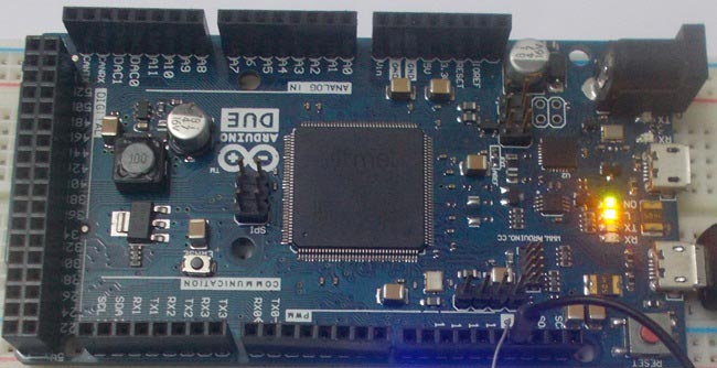
There are different types of ARDUINO boards in the market, with UNO being the most popular and DUE being the most sophisticated. DUE core is from “SAM3X8E” controller as shown in figure. This controller works at 84 MHz clock, which is more than 5 times the speed of UNO. With almost 60 GPIO (General purpose Input Output) we can use this board at will, without any need of shift registers. We have already covered many Arduino and Arduino Uno Projects, from beginner to advanced level and they cover almost all topics to learn Arduino from scratch.
UNO designed from ATMEGA controller, which is 8 bit type, and DUE designed from ARM type, which is a 32 bit type. This number itself differentiates the achievement, power and speed gap between two boards. We chose DUE board because it is the easiest way to understand ARM controller especially for starters. So in this tutorial we are going to Blink a LED using Arduino Due, for getting started with Arduino Due Board. This Program and tutorial will also goes with Arduino Uno to blink LED with it. The software and download, upload process are same for the Uno.
The ARDUINO DUE boards also possess Shield boards, they are basically extensions for ARDUINO. These shields add additional features to the ARDUINO. These shields are stacked one over the other on ARDUINO.
Required Components:
Hardware: Arduino Due board, connecting pins, 220Ω resistor, LED, bread board.
Software: Arduino nightly, download it from this link: https://www.arduino.cc/en/Main/Software
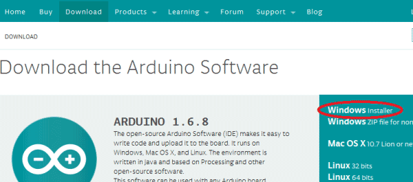
Open the above given link, under download session, we have the latest version of ARDUINO software, which is 1.6.8 (at the time of writing this article). Even if you have the older version, download the newer version. In previous versions the DUE board libraries are not present. So the previous versions cannot detect the DUE board. You can update the previous version to get the DUE board working.
Click on the windows installer button for the software:
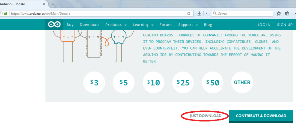
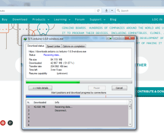
Now click on the just download button for the setup to start downloading. The setup file would be around 85 Mb.
After download install the file by double click. Once the install is complete, you will get a icon on the desktop as shown below.
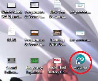
Double click on the program to start.
Now you see, there are two connectives on the DUE board.
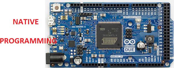
Both of the ports can be used to program the DUE, but we are going to use NATIVE USB port. Now connect the USB plug and connect the other end to PC, you should see the power LED ON.
Once the ARDUINO program is running, you should choose the ARDUINO DUE board from the ‘TOOLS’ menu of the program. Once you choose the DUE board you will see the selected board at the right bottom, as shown in the figure given below in next section.
We connected the USB to NATIVE port, so we have to choose the ‘NATIVE port’ in the software. This option will also be in ’TOOLS’ option. Once you select it, you are ready to upload the program.
Circuit and Working Explanation:

In here we are going to write a program to blink an LED for every 1000ms.We will connect an LED at PIN13 through a 220Ω current limiting resistor.
Now upload the program by clicking on the Upload Button, shown in the figure (top left corner),
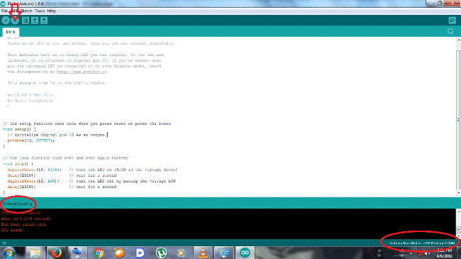
Once you successfully upload the program, at the left bottom of the screen you will see ’DONE UPLOADING’ and LED will start blinking.
It is important to remember that the GPIO of this board has a voltage limit of 3.3V. So we cannot expect voltages higher than 3.3V nor can we give voltages higher than 3.3V to any pin of this board. If voltage higher than 3.3v is given to board then it could damage the board permanently.
Check the Code below to get better understanding.
Complete Project Code
void setup()
 {
  // initialize digital pin 13 as an output.

pinMode(13, OUTPUT);
 }
// the loop function runs over and over again forever
void loop()
{

digitalWrite(13, HIGH);   // turn the LED on (making the voltage level HIGH)

delay(1000);              // wait for a second

digitalWrite(13, LOW);    // turn the LED off (making the voltage level LOW)

delay(1000);              // wait for a second
}
