
A latch circuit can ‘hold’ the circuit in either on or off state until any external signal is applied to it. Latch circuit retains its position (either on or off) even after the input signal is removed and can store one bit of information as long as the device is powered. For active high signal, it stores one, and for active low signal, it stores zero.
In this project, we are going to make a Soft Latch Circuit to turn on and off an electronic device by pushing a single button. This circuit is known as a Soft Latch Switch. A Soft Latch circuit is different from the normal latching circuit, in soft latch the on and off states can be changed using external means (push button) but in normal latching circuit, the circuit can only be latched to only one state, and to change the state the power supply need to be removed. Generally shift registers and Flip-flops are used in latching circuit, like one we have used in Clap-on-Clap-off Circuit.
Latching can be compared to Push-on-Push-off button where push button connects the circuit when pressed one time and disconnects the circuit when pressed again. Here we will use a BC547 NPN transistor and BC557 PNP transistor with a normal push-button to build a soft latching power switch. This soft latch circuit doesn’t require any microcontroller or any IC to turn it on and off.
Components Required
- Transistors: BC547(2), BC557
- Resistors: 1MΩ, 470KΩ, 220KΩ (2), 100KΩ (2), 10KΩ, 1KΩ, 330 Ω
- Push Button
- 1µF Capacitor
- LED
- Breadboard
Circuit Diagram

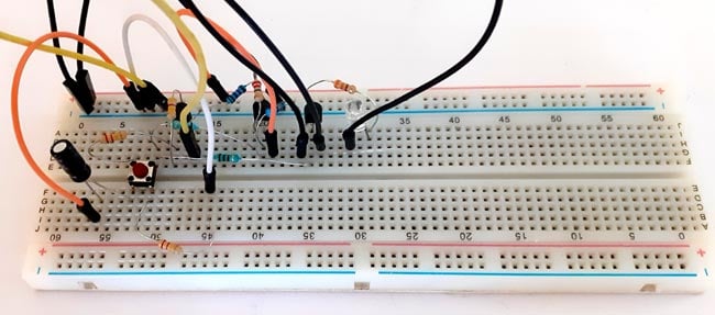
Circuit diagram for soft latching power switch circuit is given above. It can be easily built on a breadboard or PCB. Components used in this circuit are easily available and very cheap. Resistors are used as current limiting resistors while the Capacitor is used to prevent false triggering of circuit.
Working of the Soft Latch Switch Circuit
Transistor BC547 is an NPN transistor while BC557 is a PNP transistor. BC547 transistor can be turned on by applying a positive voltage to its base; on the other hand, BC557 can be turned on by applying a negative voltage to its base.
When we first apply the supply voltage by pressing the push button, all three transistors are in off condition, and the output voltage is zero; thus, the circuit remains in its off or unlatched state. In this condition capacitor, C1 charges through R1 and R2 resistor. When we press the push button switch, it causes capacitor C1 to pass its voltage to the base of the transistor Q3 through the R6 resistor. This turns on the Q3 transistor, and Q3 transistor turns on the Q2 transistor. The voltage developed across the R4 resistor will keep Q2 turned on when the button is released. Q1 also turn on during this time, and the circuit is now in the on or latched state and remains that way even though S1 is open.
At this state transistor, Q1 is now saturated, causing C1 to discharge via R2. When we press the push button switch again, capacitor C1 is in a discharged condition and will pass the zero voltage to the transistor Q3, causing the transistor to turn off. As a result, all the three transistors are in off condition, and circuit returns to its off or unlatched condition again. As Q1 is now off, capacitor C1 begins to charge via R1 and R2 resistor again. So every press of switch follows the same procedure to turn on and off the circuit.
Capacitor is used to limit the speed of the latching process. Without the capacitor circuit will turn on and off way to fast. Values of resistors and capacitor can vary according to the applications.
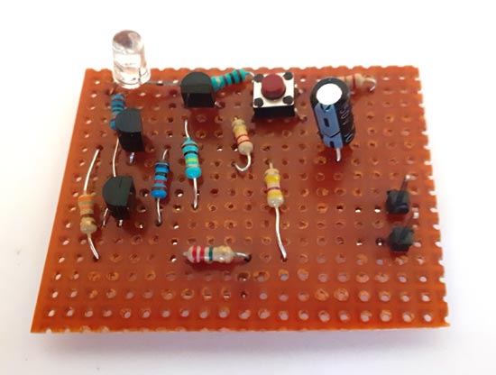
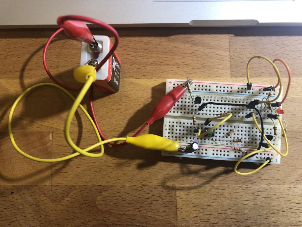
I made this soft latch switch circuit on both breadboard and perfboard, and after the complete connections on perfboard, my hardware looked like this:
Applications of the Soft Latching Circuit
- The soft latch circuit is well suited for battery-operated portable instruments as it has zero voltage in the off state.
- Soft latch circuit can be used to auto-power off the ESP32, ESP8266, Arduino, or any other microcontroller.
- Latch circuit can be very useful in alarm circuits.
Comments
Nice circuit. I appreciate
Nice circuit. I appreciate the explanation. Well done!
I used the exact components…
I used the exact components and tried to prototype the circuit on a breadboard but it does not soft-latch. The circuit does not power on by its own when battery is connected. When the momentary button is pressed the LED just lights up and switches itself off, the same happens even when the momentary button is kept pressed.
Coming very late to this…
Coming very late to this schematic but am hoping someone may still see my post and be able to help. II have breadboarded this circuit and have it working. I have found for my setup a 4.7uF capacitor gives me a more consistent/controllable on/off when pressing my momentary switch I also notice however when I switch the circuit on the LED flashes very brightly before settling back to a more normal condition. I assume the flash is because of an intial high voltage burst but cant see where that is coming from from unless it is the very brief moment between Q3 turning on Q1 and Q2 but I may may be way off base. I am running the circuit at 9v.
Any comments or advice wuld be greatly appreiated. Cheers

What's the maximum voltage it can work with