

Frequency to voltage converter converts the frequencies or pulses to the proportional electrical output such as voltage or current. It is an important tool for electromechanical measurements where repeated events are occurring. So, when we provide a frequency across a frequency to voltage converter circuit, it will provide a proportional DC output. Here we are using KA331 IC to build a frequency to voltage converter circuit.
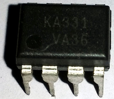
KA331 IC
KA331 is a voltage to frequency converter which is used to make a simple low-cost analog to digital converter, but it can also be used as a frequency to voltage converter. The 8 pin DIP IC can work in a wide range of bandwidth from 1Hz to 100 KHz. It also has a wide range of supply voltage from 5V to 40V. KA331 is the equivalent to popular LM331. LM331 can also be used this F-to-V circuit.
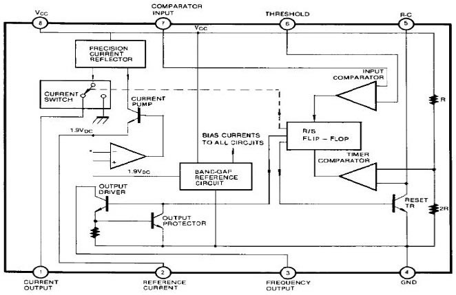
Below is pin diagram and internal circuit of the KA331 taken from the datasheet,
Required Material
- KA331 IC - 1pc
- .01uF ceramic capacitor - 1pc
- 470pF ceramic capacitor - 1pc
- 1uF Electrolytic capacitor with a 16V rating
- 10k resistor with 1% stability rating MFR - 2pcs
- 100k resistor with 1% stability rating MFR - 2pcs
- A 68k resistor with 1% stability rating MFR - 1pc
- A 6.8k resistor with 1% stability rating MFR - 1pc
- Breadboard
- 15V power supply
- Single strand wire
- A frequency generator or function generator to check the overall circuit.
Schematic diagram

Working of Frequency to Voltage Circuit
The main component of the circuit is KA331. The input of the circuit is connected across a 470pF capacitor C1, which is further connected to the threshold pin of KA331 (pin 6). Resistor R3 and R4 are forming the Voltage Divider Circuit which is connected to Comparator PIN 7 of KA331. Capacitor C3 and Resistor R5 is the RC timer which provides the required oscillation across the pin 5. Resistor R2 is providing the reference current across the pin 2. The circuit is supplied with 15v voltage which is connected across the pin 8 of KA331.
To calculate the output voltage of the circuit, the formula is –
Vout = finput x Reference voltage x (RL/RS) x (Rt x Ct)
Where finput is the frequency, RL is the load resistor, RS is the current source resistor, Rt and Ct is the resistor and capacitor of the RC oscillator.
Therefore, for our circuit, the formula will be –
Vout = finput x Reference voltage x (R6/R2) x (R5 x C3)
As per the datasheet, the reference voltage of KA331 is 1.89V. So, if we provide 500 Hz of input signal across the circuit to get the output voltage –
Vout = 500 x 1.89 x (100k/100k) x (6.8k x 0.001uf)
Vout = 500 x 1.89 x 1 x (6800k x 10-8)
Vout = 0.064V or 64mV
So, When a 500 Hz frequency applied across the circuit, the circuit will provide 64 mV output.
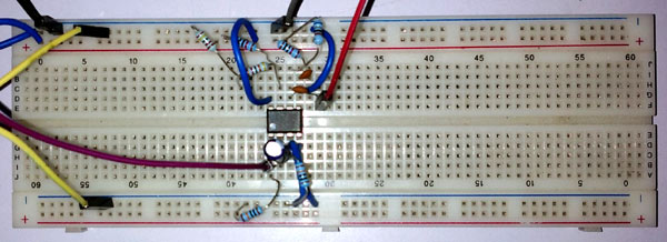
Here we have constructed the circuit on the breadboard.
Testing of Frequency to Voltage Circuit
To test the circuit, following tools are used –
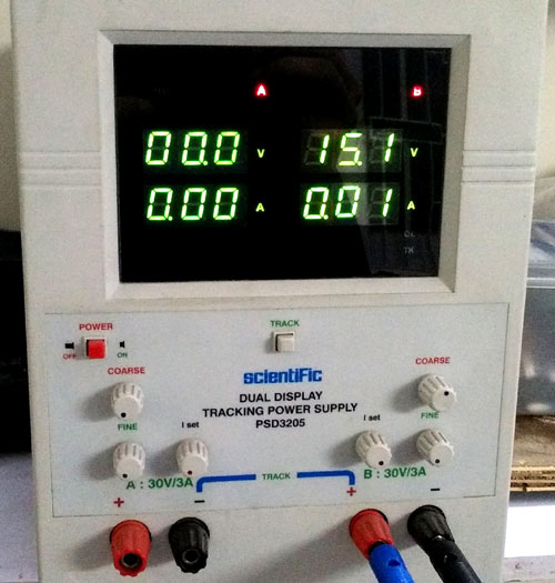
- Scientific PSD3205 bench power supply.
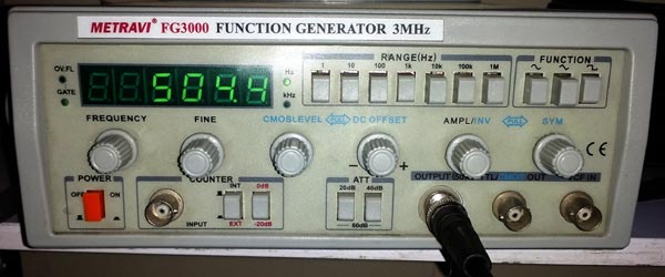
- Metravi FG3000 function generator.
- UNI-T UT33D multimeter.
The circuit is constructed using 1% Metal Film Resistors and the capacitors tolerances are not taken into account. The room temperature was 22 degree Celsius during the testing.
To test the circuit, the bench power supply is set at the 15V output.
The Function generator is providing approx 500 Hz as a square wave output.
For those who do not have access to the function generator, a timer circuit can be constructed using the classic LM555 IC or an Arduino can also be used to build function generator. However, the Android app can also work where signals are generated through the headphone output.
The Multi-meter is connected across the output and the range is selected as mili-volt.
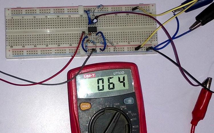
The output of the multimeter is showing the calculated value. The circuit is giving 64 mV output when 500 Hz square wave is supplied across the input.
The detailed working video is given at the end, where multiple inputs are given and the output voltage is changed in the ratio of the input voltage.

Improvements
This Frequency to Voltage Converter Circuit can be constructed on a PCB for better accuracy. The critical section of the circuit is the RC oscillator. The RC oscillator needs to be placed in a close distance across the KA331 IC. In long distance, the copper trace could drift the oscillation as it will add up additional resistance and also contribute stray capacitance. The proper Ground plane is also required.
Applications
Frequency to voltage converter is used in measurements and instrumentation like Tachometer uses Frequency to voltage converter to calculate the speed of a motor. Different kind of gauge meters, speedometers also use this technique.

Would I use 5V to supply the IC?