

From the assembly line of automobile manufacturing industries to the telesurgery robots in space, Robotic Arms are to be found everywhere. The mechanisms of these robots are similar to a human which can be programmed for similar function and increased capabilities. They can be used to perform repeated actions faster and accurate than humans or can be used in harsh environments without risking human life. We have already built a Record and Play Robotic Arm using Arduino which could be trained to do a particular task and made to repeat forever.
In this tutorial we will use the industry standard PIC16F877A 8-bit Microcontroller to control the same robotic arm with potentiometers. The challenge with this project is that PIC16F877A has only two PWN capable pins, but we need to control about 5 servo motors for our robot which requires 5 individual PWM pins. So we have to utilize the GPIO pins and generate PWM signals on PIC GPIO pins using the timer interrupts. Now, of course we could upgrade to a better microcontroller or use a de-multiplexer IC to make things a lot easier here. But still, it is worth giving this project a try for the learning experience.
The mechanical structure of the robotic arm that I am using in this project was completely 3D printed for my previous project; you can find the complete design files and assembling procedure here. Alternatively, if you do not have a 3D printer you can also build a simple Robotic Arm using cardboards as show in the link. Assuming that you have somehow got hold of your robotic Arm lets proceed into the project.
Circuit Diagram
The Complete circuit diagram for this PIC Microcontroller based Robotic Arm is shown below. The schematics was drawn using EasyEDA.

The circuit diagram is pretty simple; the complete project is powered by the 12V adapter. This 12V is then converted to +5V using two 7805 Voltage regulators. One is labeled as +5V and the other is labeled as +5V(2). The reason for having two regulators is that when the servo rotates it pulls in a lot of current which creates a voltage drop. This voltage drop forces the PIC to restart itself, hence we cannot operate both the PIC and the servo motors on the same +5V rail. So the one labeled as +5V is used to power the PIC Microcontroller, LCD and Potentiometers and a separate regulator output which is labeled as +5V(2) is used to power the servo motors.
The five output pins of the potentiometers which provide a variable voltage from 0V to 5V are connected to the analog pins An0 to AN4 of the PIC. Since we are planning to use timers to generate PWM the servo motors can be connected to any GPIO pin. I have selected pins form RD2 to RD6 for the servo motors, but it can be any GPIO of your choice.
Since the program involves a lot of debugging, a 16x2 LCD display is also interfaced to portB of the PIC. This will display the duty cycle of the servo motors that are being controlled. Apart from this I have also extended connections for all GPIO and analog pins, just in case if any sensors need to be interfaced in future. Finally I have also connected the programmer pin H1 to directly program the PIC with pickit3 using the ICSP programming option.
Generating PWM signals on GPIO pin for Servo Motor Control
Once the circuit is ready we have to figure out how to generate PWN signals on the GPIO pin of PIC to control the servo motor. We have already tired something similar using the Timer interrupt method and were successful. Here we are just going to build on top of it, so if you are new here, I would strongly recommend you to read this previous tutorial before proceeding further.
All hobby servo motors work with a frequency of 50Hz. Meaning one complete pulse cycle for a servo motor will be 1/50 (F=1/T) which is 20ms. Of this complete 20ms the control signal is only from 0 to 2ms while the rest of the signal is always off. The below figure shows how the ON time varies only from 0 to 2ms to rotate the motor from 0 degree to 180 degree of the total 20ms duration.
With this in mind we have to write the program in such a way that the PIC reads in 0 to1204 from the potentiometer and maps it to 0 to 100 which will be the duty cycle of the servo motor. Using this duty cycle we can calculate the ON time of the servo motor. Then we can initialize the timer interrupt to overflow at a regular interval such that it acts similar to the millis() function in Arduino. With that, we can toggle the status GPIO pin to be high for a desired duration and turn it off after 20ms (one complete cycle) and then repeat the same process. Now, that we have understood the logic let us get into the program.
Programming PIC16F8771A for Robotic Arm
Like always the complete program with a Video can be found at the end of this page, code can also be downloaded from here with all the necessary files. In this section we will discuss the logic behind the program. The program employs the ADC module, Timer Module and LCD Module to control the Robotic Arm. If you are not aware of how to use the ADC features or Timer features or to interface an LCD with PIC, then you can fall back to the respective links to learn them. The below explanation is given assuming that the reader is familiar with these concepts.
Timer 0 Port Configuration
The most important section in the code is setting the Timer 0 to over flow for every specific delay. The formulae to calculate this delay can be given as
Delay = ((256-REG_val)*(Prescal*4))/Fosc
By using the OPTION_REG and TMR0 register we have set the Timer 0 to operate with a prescalar value of 32 and the REG val is set to 248. The crystal frequency (Fosc) used in our hardware is 20Mhz. With these values the delay can be calculated as
Delay = ((256-248)*(32*4)) / (20000000)
           = 0.0000512 seconds (or)
           = 0.05 msec
So now we have set the timer to overflow at every 0.05ms. The code to do the same is given below
/*****Port Configuration for Timer ******/
    OPTION_REG = 0b00000100; // Timer0 with external freq and 32 as prescalar // Also Enables PULL UPs
    TMR0=248;       // Load the time value for 0.0001s; delayValue can be between 0-256 only
    TMR0IE=1;       //Enable timer interrupt bit in PIE1 register
    GIE=1;          //Enable Global Interrupt
    PEIE=1;         //Enable the Peripheral Interrupt
    /***********______***********/
Of the total 0ms to 2ms control window of the servo motor we can control it with a resolution of 0.05msec, which allows us to have (2/0.05) 40 different positions for the motor between 0 degree to 180 degree. You can decrease this value further if your MCU could support it to obtain more positions and precise control.
Interrupt Service Routine (ISR)
Now that we have the Timer 0 set to over flow for every 0.05ms, we will have the TMR0IF interrupt flag set for 0.05ms. So inside the ISR function we can reset that flag and increment a variable called count by one. So now this variable will be increment by 1 for every 0.05ms.
void interrupt timer_isr()
{
    if(TMR0IF==1) // Timer flag has been triggered due to timer overflow -> set to overflow for every 0.05ms
    {
        TMR0 = 248;     //Load the timer Value
        TMR0IF=0;       // Clear timer interrupt flag
        count++; //Count increments by 1 for every 0.05ms
    }
Calculating Duty Cycle and On Time
Next we have to calculate the duty cycle and on time for all five servo motor. We have five servo motors each of which is used to control individual section of arm. So we have to read the ADC value of all five and calculate the duty cycle and on time for each.
The ADC value will be in range of 0 to 1024 which can be converted to 0% to 100% duty cycle by simply multiplying 0.0976 (100/1024 = 0.0976) to the obtained value. This 0 to 100% duty cycle has to be then converted to ON time. We know that at 100% duty cycle the ON time has to be 2ms (for 180 degree) so multiplying 0.02 (2/100 = 0.02) will convert 0 to 100 duty cycle to 0 to 2ms. But then our timer variable count is set to increase once for every 0.05ms. This means that value of count will be 20 (1/0.05 = 20) for every 1ms. So we have to multiply 20 with 0.02 to calculate the exact on time for our program which will give us the value 0.4 (0.02*20 = 0.4). The code for the same is show below, you can see it repeated for 5 times for all 5 pot using a for loop. The resulting values are stored in the T_ON array.
for (int pot_num=0; pot_num<=3; pot_num++)
        {
        int Pev_val = T_ON[pot_num];

        POT_val = (ADC_Read(pot_num)); //Read the value of POT using ADC
        Duty_cycle = (POT_val * 0.0976); //Map 0 to 1024 to 0 to 100
        T_ON[pot_num] = Duty_cycle* 0.4;//20*0.02
Selecting which motor to rotate
We cannot control all five motors together as it will make the ISR code heavy slowing down the entire microcontroller. So we have to rotate only one servo motor at a time. To select which servo to rotate the microcontroller monitors the ON time of all five servo motors and compares it with it’s previous on time. If there is a change in the ON time then we can conclude that the particular servo has to be moved. The code for the same is shown below.
   if (T_ON[pot_num] != Pev_val)
        {
             Lcd_Clear();
            servo = pot_num;
            Lcd_Set_Cursor(2,11); Lcd_Print_String("S:");Lcd_Print_Char(servo+'0');
        if (pot_num==0)
        {Lcd_Set_Cursor(1,1); Lcd_Print_String("A:");}
        else if (pot_num==1)
        {Lcd_Set_Cursor(1,6); Lcd_Print_String("B:");}
        else if (pot_num==2)
        {Lcd_Set_Cursor(1,11); Lcd_Print_String("C:");}
        else if (pot_num==3)
        {Lcd_Set_Cursor(2,1); Lcd_Print_String("D:");}
        else if (pot_num==4)
        {Lcd_Set_Cursor(2,6); Lcd_Print_String("E:");}

        char d2 = (Duty_cycle) %10;
        char d1 = (Duty_cycle/10) %10;
        Lcd_Print_Char(d1+'0');Lcd_Print_Char(d2+'0');
We also print the servo duty cycle on the LCD screen so the user could be aware of its current position. Based on the change in ON time the variable servo is updated with numbers from 0 to 4 each representing individual motors.
Controlling the Servo Motor inside the ISR
Inside the ISR we have the variable count getting incremented for every 0.05ms, this means that for every 1ms the variable will be incremented by 20. Using this we have to control the pins to produce PWM signal. If the value of count is less than the on time then the GPIO of that motor is turned on using the below line
PORTD = PORTD | servo_code[servo];
Here the array servo_code[] has the pin detail of all five servo motor and based on the value in variable servo, the code for that particular servo motor will be used. It is then logically OR (|) with existing PORTD bits so that we do not disturb the values of other motor and update only this particular motor. Similarly for turning the pin off
PORTD = PORTD & ~(servo_code[servo]);
We have reversed the bit value using the logic inverse (~) operator and then have performed a AND (&) operation on the PORTD to turn off only the desired pin while leaving the other pins in their previous state. The complete code snippet is shown below.
void interrupt timer_isr()
{
    if(TMR0IF==1) // Timer flag has been triggered due to timer overflow -> set to overflow for every 0.05ms
    {
        TMR0 = 248;     //Load the timer Value
        TMR0IF=0;       // Clear timer interrupt flag
        count++; //Count increments by 1 for every 0.05ms -> count will be 20 for every 1ms (0.05/1 = 20))
    }

    int servo_code[] = {0b01000000, 0b00100000, 0b00010000, 0b00001000, 0b00000100 };
    if (count >= 20*20)
    count=0;

     if (count <= (T_ON[servo]) )
         PORTD = PORTD | servo_code[servo];
     else
         PORTD = PORTD & ~(servo_code[servo]);
}
We know that the total cycle has to last for 20ms before the GPIO pin is turned on again. So we check if the count has exceeded 20ms by comparing the value of count with 400 (same calculation as discussed above) and if yes we have to initialize the count to be zero again.

Simulation of PIC Robotic Arm Code
It is always better to simulate the code before taking it to the real hardware. So I used Proteus to simulate my code and verified it to work correctly. The circuit used for simulation is shown below, We have used an oscilloscope to check if the PWM signals are being generated as required. Also we can verify if the LCD and Servo motors are rotating as expected.
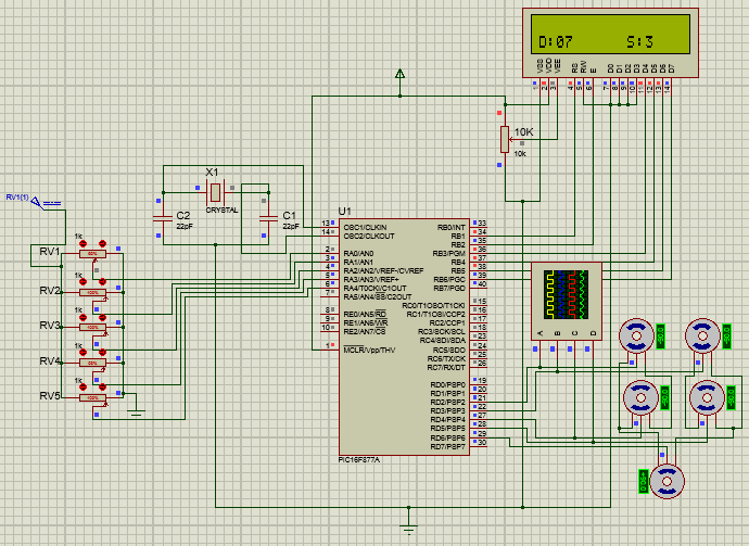
As you can see the LCD displays the duty cycle of motor D to be 07 based on the pot value which is the 3rd motor. Similar if another pot is moved the duty cycle of that pot and its motor number will be displayed on the LCD. The PWM signal shown on the oscilloscope is shown below.
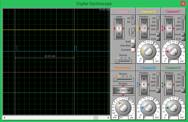
The total cycle period is measured to be 22.2ms using the cursor option on the oscilloscope, which is very close to the desired 20ms. Finally we are sure that the code works, so to continue with the circuit we can either solder it on a perf board or use a PCB. It will not work easily on breadboard because the POT always tends to give some problems due to poor connections.
PCB Design using EasyEDA
To design this PIC Robotic Arm, we have chosen the online EDA tool called EasyEDA. I have been using it for a long time now and find it very convenient because of its vast availability of footprint and easy to use nature. After designing the PCB, we can order the PCB samples by their low cost PCB fabrication services. They also offer component sourcing service where they have a large stock of electronic components and users can order their required components along with the PCB order.
While designing your circuits and PCBs, you can also make your circuit and PCB designs public so that other users can copy or edit them and can take benefit from your work, we have also made our whole Circuit and PCB layouts public for this circuit, check the below link:
https://easyeda.com/circuitdigest/pic-development-board-for-robotic-arm
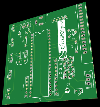
Using this link you can directly order the same PCB that we are using in this project and use it. Once the design is complete the board can be viewed as 3D model which will be very much helpful in visualizing how the board would appear after fabrication. The 3D model of the board that we are using is shown below. Apart from this you can also view the top and bottom layer of the board to check if the slick screen is as expected.
Calculating and Ordering Samples online
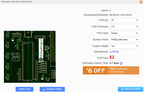
After completing the design of this PIC Robot PCB, you can order the PCB through JLCPCB.com. To order the PCB from JLCPCB, you need Gerber File. To download Gerber files of your PCB just click the Generate Fabrication File button on EasyEDA editor page, then download the Gerber file from there or you can click on Order at JLCPCB as shown in below image. This will redirect you to JLCPCB.com, where you can select the number of PCBs you want to order, how many copper layers you need, the PCB thickness, copper weight, and even the PCB color, like the snapshot shown below:
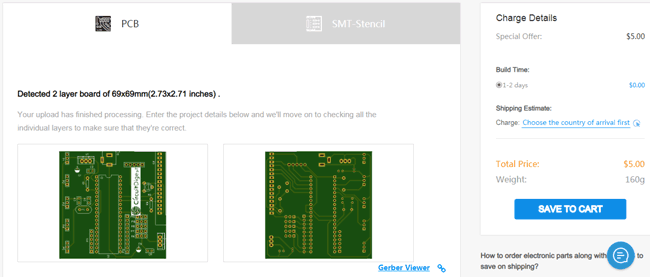
After you have selected all of the options, click “Save to Cart” and then you will be taken to the page where you can upload your Gerber File which we have downloaded from EasyEDA. Upload your Gerber file and click “Save to Cart”. And finally click on Checkout Securely to complete your order, then you will get your PCBs a few days later. They are fabricating the PCB at very low rate which is $2. Their build time is also very less which is 48 hours with DHL delivery of 3-5 days, basically you will get your PCBs within a week of ordering.
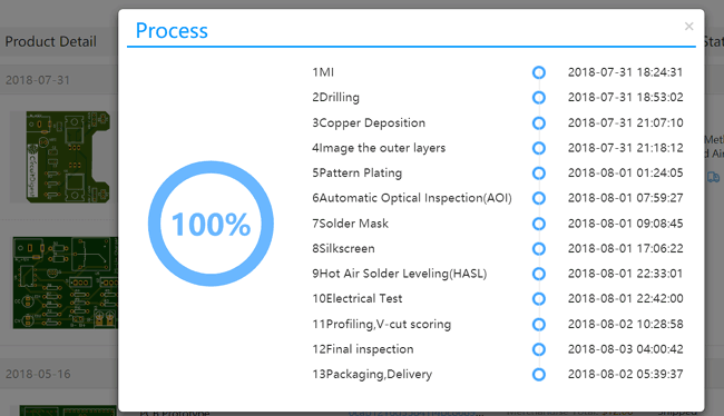
After ordering the PCB, you can check the Production Progress of your PCB with date and time. You check it by going on Account page and click on "Production Progress" .
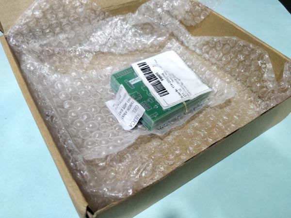
After few days of ordering PCB’s I got the PCB samples in nice packaging as shown in below pictures.
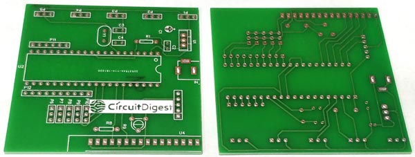
And after getting these pieces I have soldered all the required components over the PCB. I also directly soldered the POT directly instead of using connecting wires because the female to female wires that I initially used where giving weird analog output voltages probably because of loose contacts. Once all the components were assembled my PCB looked something like this.
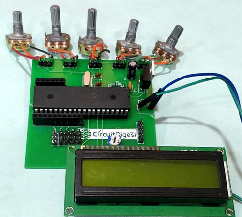
You might have noticed that there is only one 7805 on this board. That is because initially I thought I could get away with just regulator for powering both PIC and servo motor and later I realized I need two. So I have used an external circuit to power the servo motors through the green wires you see here.
Nevertheless you don’t have to worry much about it because; I have made the changes to the PCB now. You can make use of the modified PCB and solder both the regulators on board itself.
Working of PIC Robotic Arm
After all the tiring work it is time for pay off. Solder all the components on the board and upload the program to the PIC controller. Complete Code is given below or can be downloaded from here. The programming connector provided on the board should help you upload the program directly using Pickit 3 without much hassle. Once the program is uploaded you should see the LCD displaying the servo that is currently being controlled. To learn more about programming the PIC Microcontroller, just follow the previous tutorial.
From there you can simply turn the pot and check how the servo motors respond each potentiometer. Once you understand the format you can control the robotic arm to perform whatever action you need it to perform and have fun. You can find the complete working of the project in the video linked below.
That is it guys hope you understood the project and learnt something new from it. If you have any questions leave them in the comment section or use the forums for other technical discussions.
Complete Project Code
/*

 * Program to Control Robotic Arm through POT

 * 5 Servo controlled with Timer Register PWM

 * Dated: 15-1-2019

 * Web: www.circuitdigest.com

 * Author: B.Asiwnth Raj

 */
#pragma config FOSC = HS        // Oscillator Selection bits (HS oscillator)

#pragma config WDTE = OFF       // Watchdog Timer Enable bit (WDT disabled)

#pragma config PWRTE = ON       // Power-up Timer Enable bit (PWRT enabled)

#pragma config BOREN = ON       // Brown-out Reset Enable bit (BOR enabled)

#pragma config LVP = OFF        // Low-Voltage (Single-Supply) In-Circuit Serial Programming Enable bit (RB3 is digital I/O, HV on MCLR must be used for programming)

#pragma config CPD = OFF        // Data EEPROM Memory Code Protection bit (Data EEPROM code protection off)

#pragma config WRT = OFF        // Flash Program Memory Write Enable bits (Write protection off; all program memory may be written to by EECON control)

#pragma config CP = OFF         // Flash Program Memory Code Protection bit (Code protection off)
#define _XTAL_FREQ 20000000 //Crystak Freq is 20MHz

#define PWM_Frequency 0.05 // in KHz (50Hz)
//Define LCD pins

#define RS RB1

#define EN RB2

#define D4 RB3

#define D5 RB4

#define D6 RB5

#define D7 RB6
#include <xc.h>

#include "lcd.h" //Header for using LCD module
int POT_val; //variable to store value from ADC

int count; //timer variable

//int T_TOTAL = (1/PWM_Frequency); //calculate Total Time from frequency (in milli sec)) //20msec

int Duty_cycle; //Duty cycle value

int T_ON[4];
char servo;
void ADC_Initialize() //Prepare the ADC module

{

  ADCON0 = 0b01000001; //ADC ON and Fosc/16 is selected

  ADCON1 = 0b11000000; // Internal reference voltage is selected

}
unsigned int ADC_Read(unsigned char channel) //Read from ADC

{

  ADCON0 &= 0x11000101; //Clearing the Channel Selection Bits

  ADCON0 |= channel<<3; //Setting the required Bits

  __delay_ms(2); //Acquisition time to charge hold capacitor

  GO_nDONE = 1; //Initializes A/D Conversion

  while(GO_nDONE); //Wait for A/D Conversion to complete

  return ((ADRESH<<8)+ADRESL); //Returns Result

}
void interrupt timer_isr()

{

    if(TMR0IF==1) // Timer flag has been triggered due to timer overflow -> set to overflow for every 0.05ms

    {

        TMR0 = 248;     //Load the timer Value

        TMR0IF=0;       // Clear timer interrupt flag

        count++; //Count increments by 1 for every 0.05ms

    }


    int servo_code[] = {0b01000000, 0b00100000, 0b00010000, 0b00001000, 0b00000100 };


    if (count >= 20*20)

    count=0;


     if (count <= (T_ON[servo]) )

         PORTD = PORTD | servo_code[servo];

     else

         PORTD = PORTD & ~(servo_code[servo]);

}

void main()

{

    /*****Port Configuration for Timer ******/

    OPTION_REG = 0b00000100;  // Timer0 with external freq and 32 as prescalar // Also Enables PULL UPs

    TMR0=248;       // Load the time value for 0.0001s; delayValue can be between 0-256 only

    TMR0IE=1;       //Enable timer interrupt bit in PIE1 register

    GIE=1;          //Enable Global Interrupt

    PEIE=1;         //Enable the Peripheral Interrupt

    /***********______***********/


    /*****Port Configuration for I/O ******/

    TRISB = 0x00; //PORT B is output since LCd is connected

    PORTB=0x00; //Initialize all pins to 0

    TRISD = 0x00; //PORT D is output since servo is connected

    PORTD=0x00; //Initialize all pins to 0

    /***********______***********/


    Lcd_Start(); //Initialize LCD module

    ADC_Initialize(); //Initialize ADC module


   // Lcd_Clear();

   // Lcd_Set_Cursor(1,1);

    //Lcd_Print_String("Circuit Digest");

    //Lcd_Set_Cursor(2,1);

    //Lcd_Print_String("WORKING!!");

    //__delay_ms(500);


    while(1)

    {

        for (int pot_num=0; pot_num<=3; pot_num++)

        {

        int Pev_val = T_ON[pot_num];


        POT_val = (ADC_Read(pot_num)); //Read the value of POT using ADC

        Duty_cycle = (POT_val * 0.0976); //Map 0 to 1024 to 0 to 100

        T_ON[pot_num] = Duty_cycle* 0.4;//((Duty_cycle * T_TOTAL) / 1000)*10; //Calculate On Time from 0ms to 2ms for 0-100 Duty Cycle //*10 is multiplication factor


        if (T_ON[pot_num] != Pev_val)

        {

             Lcd_Clear();

            servo = pot_num;

            Lcd_Set_Cursor(2,11); Lcd_Print_String("S:");Lcd_Print_Char(servo+'0');


        if (pot_num==0)

        {Lcd_Set_Cursor(1,1); Lcd_Print_String("A:");}

        else if (pot_num==1)

        {Lcd_Set_Cursor(1,6); Lcd_Print_String("B:");}

        else if (pot_num==2)

        {Lcd_Set_Cursor(1,11); Lcd_Print_String("C:");}

        else if (pot_num==3)

        {Lcd_Set_Cursor(2,1); Lcd_Print_String("D:");}

        else if (pot_num==4)

        {Lcd_Set_Cursor(2,6); Lcd_Print_String("E:");}


        char d2 = (Duty_cycle) %10;

        char d1 = (Duty_cycle/10) %10;

        Lcd_Print_Char(d1+'0');Lcd_Print_Char(d2+'0');


        }


       }


    }

}
Comments
Robotic Arms
Hello Mr. Aswinth,
I have her circuit for controlling her robotic arm
rebuilt and used their program without modification to the test of the circuit.
SR2-SR5 work as well as the LCD display
from A-D everything OK. but SR 1 on pin 21 of the PIC does not output a signal, likewise the display E does not show.
I rule out a wiring error
how could i find the mistake what can i do?
Many thanks for your help
With best regards
Herbert Wichmann
Which compiler did you use?
Which compiler did you use?
In PICC and Mikro C it marks me multiple errors.

Which compiler did you use?
In PICC and Mikro C it marks me multiple errors.