

The term Supercapacitors and its possible usage in Electric Vehicles, Smartphone’s and IoT devices are being considered extensively in the recent times, but the idea of super capacitor itself dates back to 1957 when it was first experimented by General Electric to increase the storage capacity of its capacitors. Over the years Super capacitor technology has improved substantially that today it is being used as battery back-ups, solar power banks and other applications where short power boost is required. Many have a misconception to consider super caps as a replacement for battery in long run, but at least with today’s technology supercapacitors are nothing but capacitors with high charge capacity, you can know more about supercapacitors from our previous articles.
In this article we will learn how to charge such super capacitors safely by designing a simple charger circuit and then use it to charge our super capacitor to check how good it is in holding energy. Similar to battery cells super capacitor can also be combined to form capacitor power banks, the approach to charge a capacitor power bank is different and is outside the scope of this article. Here will use the simple and commonly available 5.5V 1F Coin Super-capacitor that looks similar to a coin cell. We will learn how to charge coin type supercapacitor and use it in suitable applications.
Charging a Super-Capacitor
Comparing a super capacitor vaguely with a battery, super capacitors have low charge density and worse self-discharging characteristics but yet in terms of charging time, shelf life and charge cycle super capacitors outperform batteries. Based on the charging current availability super capacitors can be charged in less than a minute and if handled properly it can last for more than a decade.
Compared to batteries the super capacitors have very low ESR (Equivalent series resistance) value this allows higher value of current to flow in or out the capacitor enabling it to get charged faster or discharge with high current. But because of this capability of handling high current, a super capacitor should be charged and discharged safely to prevent thermal runaway. When it comes to charging a super-capacitor there are two golden rules, the capacitor should be charged with correct polarity and with a voltage not exceeding 90% of its total voltage capacity.
Super-capacitors in market today are normally rated for 2.5V, 2.7V or 5.5V. Just like a lithium cell these capacitors have to be connected in series and parallel combination to form high voltage battery packs. Unlike batteries a capacitor when connected in series will reciprocally sum its total voltage rating, making it necessary to add more capacitors to form battery packs of decent value. In our case we have a 5.5V 1F capacitor so the charging voltage should be 90% of 5.5 that is somewhere near 4.95V.
Energy Stored in a Super Capacitor
When using capacitors as energy storage elements to power our devices it is important to determine the energy stored in a capacitor to predict how long the device could be powered. The formulae to calculate the energy stored in capacitor can be given by E=1/2CV2 . So in our case for a 5.5V 1F capacitor when charged fully the energy stored will be
E = (1/2)* 1 * 5.52
E= 15 Joules
Now, using this value we can calculate how long the capacitor can power things, say for example if we need 500mA at 5V for 10 seconds. Then the energy required for this device can be calculated using formulae Energy = Power x time. Here Power is calculated by P=VI, so for 500mA and 5V power is 2.5 Watts.
Energy = 2.5 x (10/60*60)
Energy = 0.00694 Watt-hour or 25 Joules
From this we can conclude that we will need at least two of these capacitors in parallel (15+15=30) to get a power pack of 30 Joules which will be enough to power our device for 10 seconds.
Identifying polarity on super capacitor
When it comes to capacitor and batteries we should be very cautious with its polarity. A capacitor with inverse polarity will most likely heat and melt and sometimes burst in worst case scenarios. The capacitor that we have is of coin type, the polarity of which is indicated with small white arrow as shown below.
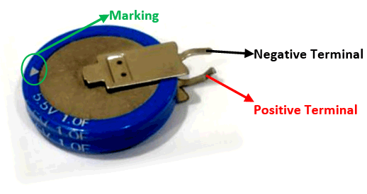
I assume that the direction of arrow indicates the direction of current. You can think of it like, current always flows from positive to negative and hence the arrow starts from positive side and points towards the negative side. Once you know the polarity and if you are curious to charge it, you can even use a RPS set it to 5.5V (or 4.95V for safety) and then connect the positive lead of RPS to positive pin and negative lead to negative pin and you should see the capacitor being charged.
Based on the current rating of the RPS you can note that the capacitor being charged within seconds and once it reaches 5.5V it will stop drawing anymore current. This fully charged capacitor can now be used in suitable application before it self-discharges.
Instead of using a RPS in this tutorial we will build a charger that regulates 5.5V form a 12V adapter and use it to charge the super capacitor. The voltage of the capacitor will be monitored using a op-amp comparator and once the capacitor is charged the circuit will automatically disconnect the super-capacitor from the voltage source. Sounds interesting right so let’s get started.
Materials Required
- 12V Adapter
- LM317 Voltage Regulator IC
- LM311
- IRFZ44N
- BC557 PNP Transistor
- LED
- Resistor
- Capacitor
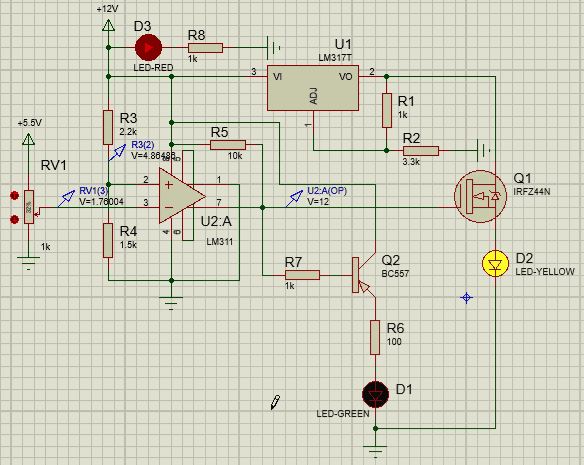
Circuit Diagram

The circuit is powered by a 12V adapter; we then use a LM317 to regulate 5.5V to charge our capacitor. But this 5.5V will be provided to capacitor through a MOSFET acting as a switch. This switch will close only if the voltage of the capacitor has less than 4.86V as the capacitor gets charges and voltage increase the switch will open and prevent the battery from getting charged further. This voltage comparison is done using an op-amp and we also use a BC557 PNP transistor to glow an LED when the charging process is complete. The circuit diagram shown above is broken into segments below for explanation.
LM317 Voltage Regulation:
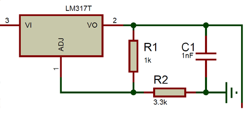
The resistor R1 and R2 is used to decide the output voltage of the LM317 Regulator based on the formulae Vout = 1.25 x (1+R2/R1). Here we have used a value of 1k and 3.3k to regulate an output voltage of 5.3V which is close enough to 5.5V. You can use our online calculator to calculate the desired output voltage based on the resistor value available with you.
Op-Amp Comparator:
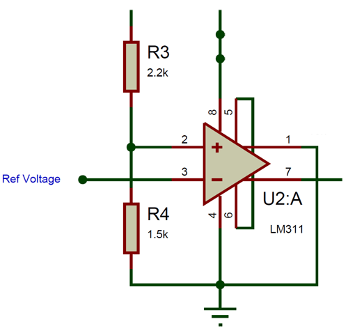
We have used the LM311 comparator IC to compare the voltage value of the super capacitor with a fixed voltage. This fixed voltage is provided to pin number 2 using a voltage divider circuit. The Resistors 2.2k and 1.5k drop a voltage of 4.86V form 12V. This 4.86 volt is compared with ref voltage (voltage of capacitor) which is connected to pin 3. When the ref voltage is lesser than 4.86V the output pin 7 will go high with 12V with the pull-up 10k resistor. This voltage will then be used to drive the MOSFET.
MOSFET and BC557:
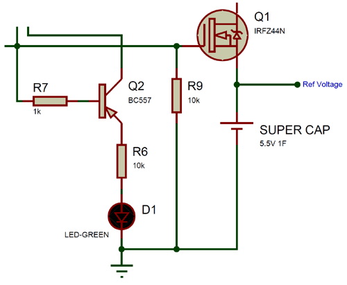
The IRFZ44N MOSFET is used to connect the super capacitor to charging voltage based on the signal from the op-amp. When the op-amp goes high it outputs 12V on pin 7 which turns on the MOSFET through its base pin similarly when op-amp goes low (0V) the MOSFET will be opened. We also have a PNP transistor BC557 which will turn on the LED when the MOSFET is off indicating that the capacitor voltage is more than 4.8V.

Simulation of Supercapacitor Charger Circuit
To simulate the circuit I have replaced the battery with a variable resistor to provide a variable voltage to pin 3 of op-amp. The Super capacitor is replaced with a LED to show if it powered or not. The simulation result can be found below.
As you can see as using the voltage probes, when the voltage on inverting pin is low than non-inverting pin the op-amp goes high with 12V on pin 7 which turns on the MOSFET and thus charges the capacitor (yellow LED). This 12V also triggers the BC557 transistor to turn off the green LED. As the voltage of the Capacitor (potentiometer) increase the green LED will turn on since the op-amp will output 0V as shown above.
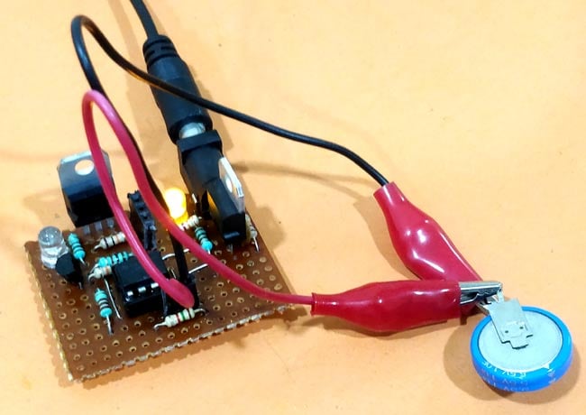
Supercapacitor Charger on Hardware
The circuit is pretty simple and can be constructed on a breadboard, but I decided to use a Perf board so that I can reuse the circuit in future in every attempt to charge my super capacitor. I also intend to use it along with solar panel for portable projects, hence tried building it as small and rigid as possible. My complete circuit once soldered on a dotted board is shown below.
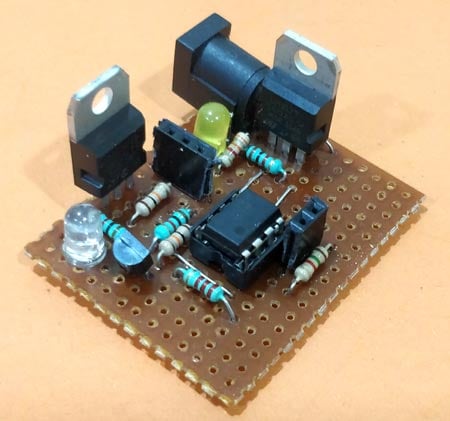
The two female berg sticks can be tapped using alligator pins to charge the capacitor. The Yellow LED indicates the power to the module and the blue LED indicates the status of charging. Once the charging process is complete the LED will lit up else will remain turned off. Once the circuit is ready simply connect the capacitor and you should see the blue LED go off and after sometime it will go high again to indicate the charging process is complete. You can see the board in charging and charged state below.

The complete working can be found in the video given at the bottom of this page, if you have any problem getting this to work post them in the comment section or use our forums for other technical questions.
Design Improvements
The circuit design given here is crude and works for its purpose; few mandatory improvements I noticed after the build are discussed here. The BC557 gets hot because of the 12V across its base and emitter so a high voltage diode should be used in place of BC557.
Secondly as the capacitor chargers the voltage comparator measures the change in voltage but when MOSFET turn off after charge the op-amp senses low voltage gain and turns on the FET again, this process is repeated few times before the op-amp turns completely off. A latching circuit on the op-amp output will solve the problem.
<p><iframe allowfullscreen="" frameborder="0" height="315" src="https://youtu.be/F9nUlEisIlw" width="560"></iframe></p>

Hey there,
Can you send me a link for your email? I have a questions about modifying an outdoor temp receiver to output the temp it receives from the wireless unit outside and output it so i can read it on an arduino or such. Any help would be wonderful!
Thanks!