
Line follower Robot is a very simple robot that follows a line, either a black line or a white line. These type of robots are very simple to build and is often the first choice for beginners who are getting started with robotics. Basically, there are two types of line follower robots: one is a black line follower which follows the black line and the second is a white line follower which follows the white line. Line follower actually senses the line and follows it. Though the idea sounds simple, with a little more development, robots similar to this are practically used in many applications like factory floor management robots or warehouse robots. We also made an Arduino UNO Line Follower Robot, you can check out the demonstration video given below:
Concepts of Line Follower
The concept of working of line follower is related to light. We use here the behavior of light at the black and white surfaces. When light falls on a white surface it is almost fully reflected and in the case of a black surface light is completely absorbed. This behavior of light is used in building a line follower robot.
In this Arduino based line follower robot, we have used IR Transmitters and IR receivers also called photodiodes. They are used for sending and receiving light. IR transmits infrared lights. When infrared rays falls on the white surface, it’s reflected back and caught by photodiodes which generate some voltage changes. When IR light falls on a black surface, light is absorbed by the black surface and no rays are reflected back, thus photo diode does not receive any light or rays. Here in this Arduino line follower robot when the sensor senses white surface then Arduino gets 1 as input and when senses black line Arduino gets 0 as input.
Since the Line follower robot is an interesting beginners project, we have also built it using different development boards other than Arduino, you can also check them out using the below link if interested
- Line Follower Robot using 8051 Microcontroller
- Line Follower Robot using Raspberry Pi
- Texas MSP430 Launchpad based Line Follower
- Simple Line Follower using PIC Microcontroller
- Line Follower using ATmega16 AVR Microcontroller
Circuit Explanation
The whole Arduino line follower robot can be divided into 3 sections: sensor section, a control section, and driver section.
Sensor section:
This section contains IR diodes, potentiometer, Comparator (Op-Amp) and LED’s. The potentiometer is used for setting reference voltage at comparator’s one terminal and IR sensors are used to sense the line and provide a change in voltage at the comparator’s second terminal. Then the comparator compares both voltages and generates a digital signal at the output. Here in this line follower circuit, we have used two comparators for two sensors. LM 358 is used as a comparator. LM358 has inbuilt two low noise Op-amps.
Control Section:
Arduino Pro Mini is used for controlling the whole the process of the line follower robot. The outputs of comparators are connected to digital pin numbers 2 and 3 of Arduino. Arduino read these signals and send commands to driver circuit to driveline follower.
Driver section:
The driver section consists of motor driver and two DC motors. The motor driver is used for driving motors because Arduino does not supply enough voltage and current to the motor. So we add a motor driver circuit to get enough voltage and current for the motor. Arduino sends commands to this motor driver and then it drives motors.
Working of Line Follower Robot using Arduino
Building a Line follower robot using Arduino is interesting. The line follower robot senses a black line by using a sensor and then sends the signal to Arduino. Then Arduino drives the motor according to sensors' output.
Here in this project, we are using two IR sensor modules namely the left sensor and the right sensor. When both left and right sensor senses white then the robot moves forward.
If the left sensor comes on a black line then the robot turn the left side.
If the right sensor sense black line then robot turn right side until both sensors comes at the white surface. When the white surface comes robot starts moving on forward again.
If both sensors come on the black line, the robot stops.
Circuit Diagram

The complete circuit diagram for arduino line follower robot is shown in the above image. As you can see the output of comparators is directly connected to Arduino digital pin number 2 and 3. And motor driver’s input pin 2, 7, 10 and 15 is connected to Arduino's digital pin number 4, 5, 6 and 7 respectively. And one motor is connected at the output pin of motor drivers 3 and 6 and another motor is connected at pin 11 and 14.
Program Explanation
In the program, first of all, we defined input and output pin, and then in loop, we check inputs and sends output according to inputs to the output pin for the driving motor. For checking the input pin we used “if” statements. The complete line follower robot code can be found at the bottom of this page.
There are four conditions in this line following robot that we read by using Arduino. We have used two sensors namely the left sensor and the right sensor.
Input | Output | Movement Of Robot | ||||
Left Sensor | Right Sensor | Left Motor | Right Motor | |||
LS | RS | LM1 | LM2 | RM1 | RM2 | |
0 | 0 | 0 | 0 | 0 | 0 | Stop |
0 | 1 | 1 | 0 | 0 | 0 | Turn Right |
1 | 0 | 0 | 0 | 1 | 0 | Turn Left |
1 | 1 | 1 | 0 | 1 | 0 | Forward |
We write the arduino line follower code according to the conditions shown in table above.

Required Components
Arduino
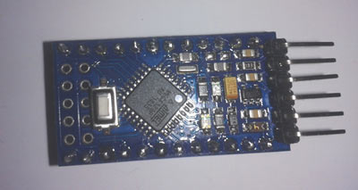
In our Project, we have used a microcontroller to control whole the process of system that is ARDUINO. Arduino is an open-source hardware and very useful for project developments. There are many types of arduino like Arduino UNO, arduino mega, arduino pro mini, Lilypad etc. available in the market. Here we have used arduino pro mini in this project as arduino pro mini is small and so breadboard compatible. To burn the line follower robot arduino code we have used an FTDI burner.
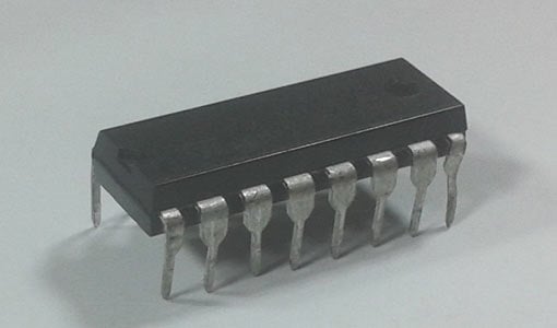
L293D Motor Driver
L293D is a motor driver IC which has two channels for driving two motors. L293D has two inbuilt Transistor Darlington pair for current amplification and a separate power supply pin for giving external supply to motors.
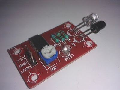
IR Module:
IR Module is sensor circuit that consists IR LED/photodiode pair, potentiometer, LM358, resistors and LED. IR sensor transmits Infrared light and photodiode receives the infrared light.
Power Supply
I have added a voltage regulator to get 5 volts for Arduino, comparator and motor driver. And a 9-volt battery is used to power the circuit.
Complete Project Code
/*------ Arduino Line Follower Code----- */
/*-------defining Inputs------*/
#define LS 2 // left sensor
#define RS 3 // right sensor
/*-------defining Outputs------*/
#define LM1 4 // left motor
#define LM2 5 // left motor
#define RM1 6 // right motor
#define RM2 7 // right motor
void setup()
{
pinMode(LS, INPUT);
pinMode(RS, INPUT);
pinMode(LM1, OUTPUT);
pinMode(LM2, OUTPUT);
pinMode(RM1, OUTPUT);
pinMode(RM2, OUTPUT);
}
void loop()
{
if(digitalRead(LS) && digitalRead(RS)) // Move Forward
{
digitalWrite(LM1, HIGH);
digitalWrite(LM2, LOW);
digitalWrite(RM1, HIGH);
digitalWrite(RM2, LOW);
}
if(!(digitalRead(LS)) && digitalRead(RS)) // Turn right
{
digitalWrite(LM1, LOW);
digitalWrite(LM2, LOW);
digitalWrite(RM1, HIGH);
digitalWrite(RM2, LOW);
}
if(digitalRead(LS) && !(digitalRead(RS))) // turn left
{
digitalWrite(LM1, HIGH);
digitalWrite(LM2, LOW);
digitalWrite(RM1, LOW);
digitalWrite(RM2, LOW);
}
if(!(digitalRead(LS)) && !(digitalRead(RS))) // stop
{
digitalWrite(LM1, LOW);
digitalWrite(LM2, LOW);
digitalWrite(RM1, LOW);
digitalWrite(RM2, LOW);
}
}
Comments
please what is the programing language am still studing 2 langauges. but for the others am fine
Will there be no headder file included in program ? if yes, can u give the complete program.And which software u used to burn program on arduino uno.
Code is complete. Arduino IDE software (Arduino Nightly : https://www.arduino.cc/en/Main/Software) used to write, verify and upload the code to arduino, through PC
Sir , plz tell how to connect the ir sensor
How many pins does your sensor have?
If 3: you can see they will be marked as follows: VCC, GND and the third pin isOutput. Connect VCC to 5V and GND to Ground and then connect the Output pin to the Analog/Digital pin of Arduino..any way u like it. If you are following this particular code then connect the output of LEFT SENSOR to digital pin 2 of your Arduino and the output of RIGHT SENSOR to digital pin 3 of the Arduino. Hope this helps!!
In case of 4 pins; the pins are: VCC, GND, Analog(A), Digital(D). In that case if you are following this code then connect the DIGITAL pins of both the sensors in the same way as above,i.e., to digital pins 2 and 3 of the Arduino...
Hope this helps!!
Best description of an LFR n the internet!!! Thanks buddy...
Hello, I m not so families with these things. But I wanted to know.. If I have IR module.. Then do I need to put all the resistance, LM358,diode etc as instructed on circuit.
I am using arduino uno, will the same code work and my robot only has 2 motors for the Weels and 2 IR sensors ( 2 receivers and 2 emitters).
This is the perfect platform whr we cn get any information related to arduino..really it is nice1
Can you plz tell me if I am doing pick and place robotic arm along with line follower what should be my code plzzzz I am using arduino mega 2560 and 4 DC motors
Hi I am making pick and place robotic arm along with line follower so can anyone help me in coding section I am using 4 DC motors 2 for base and 1for shoulder 1for wrist and I am using limit switch too plz its too much important for me
hi sir nice project
i have two ir sensor
but both a sensor are same
[i.e] connection of LM358 1st pin output
but i don't have a 7th pin output
what can i do sir
its nice.u did a good job. continue your new projects and also share .All things,connecting' s etc are shown very clearly .its very clean.sounds good....
`LS' was not declared in this scope
and arduino selects this sentence:
if(!(digitalRead(LS)) && !(digitalRead(RS))) // stop
What should i do?
Thanks.
how can i slow the speed of my motor ? i already test it but i want to slow the speed of my motor what will i do to slow down the speed ?
You can reduce the driving Voltage by using some voltage regulator like LM317.
produce some delay in program
void setup() {
// put your setup code here, to run once:
pinMode(5,OUTPUT);
pinMode(6,OUTPUT);
pinMode(7,OUTPUT);
pinMode(8,OUTPUT);
pinMode(9,INPUT);
pinMode(10,INPUT);
}
void loop() {
// put your main code here, to run repeatedly:
int s1=digitalRead(9);
int s2=digitalRead(10);
if(s1==HIGH && s2==HIGH)
{
digitalWrite(5,HIGH);
digitalWrite(6,LOW);
digitalWrite(7,HIGH);
digitalWrite(8,LOW);
}
else if(s1==HIGH&&s2==LOW)
{
digitalWrite(5,HIGH);
digitalWrite(6,LOW);
digitalWrite(7,HIGH);
digitalWrite(8,HIGH);
}
else if(s1==LOW&&s2==HIGH)
{
digitalWrite(5,LOW);
digitalWrite(6,LOW);
digitalWrite(7,HIGH);
digitalWrite(8,LOW);
}
else
{
digitalWrite(5,LOW);
digitalWrite(6,LOW);
digitalWrite(7,LOW);
digitalWrite(8,LOW);
}
}
can you please tell me this program is correct or not.
your program is correct.....
But after the finishing of the line (black or white) robot can stop for this program.robot can turn the 180 angle so which type of the else are put in the program.
Hi
can any one tell me how can we combine two codes means i am having the code for black line and another code for white line i want to combine both the cods so that if while traveling from black line when imediatly white line starts how can i combine the code please help
You can use Color Detector to detect the White and Black line and can switch the code accordingly. Check Color Detector using Arduino Uno
maybe you could add a third sensor in the middle ad add an IF statement that cheks the if the two sides sensors are sensing something and the middel sensor is sensing something else then do something (which is using the proper code for that line that is sensed by the middel sensor) that code be done by putting the two codes in external functions and calling them when needed .
Can i know how do you connect the battery ?
which component that you connect it with ? i try to understand, but i cant find the answer.
tq
Use a simple 9v Battery, and connect is according to Circuit Diagram.
Sir , could you list all the components needed for this project ? thank you .
If you'll be using arduino, what changes to the ckt will be made?
How to turn the line follower at exact 90 degree. it would be better if the reply is given the the exact code. thanks.
Basic program and setup for Line Follower Robot
Please which sensor did you use and where can i buy it
We have used 2 IR sensors or IR modules which mainly consists one IR LED and one Photo diode (Black LED type component). They are available online as well as offline on stores.
Cant upload coding in Arduino fault is showing
"Arduino: 1.8.0 (Windows 10), Board: "Arduino/Genuino Uno"
Sketch uses 1178 bytes (3%) of program storage space. Maximum is 32256 bytes.
Global variables use 9 bytes (0%) of dynamic memory, leaving 2039 bytes for local variables. Maximum is 2048 bytes.
avrdude: ser_open(): can't open device "\\.\COM1": The system cannot find the file specified.
Problem uploading to board. See http://www.arduino.cc/en/Guide/Troubleshooting#upload for suggestions.
This report would have more information with
"Show verbose output during compilation"
option enabled in File -> Preferences."
Please help
I have had this problem previously. To fix it I changed the COM port. You can do this by going to tools > port > then select the final port listed.
Thank you for sharing this.
Do you have a schematic diagram of the connection between the components?
Sir,
i have 4 way infrared tracking sensor could you please tell me how i connect this to arduino uno r3 and also tell me the code of this type infrared sensor.
can u say the program for which i can use 2 ir sensor for following black line and two ir sensor following white surface in single program plz.
if(digitalRead(LS) && !(digitalRead(RS))) // turn left
{
digitalWrite(LM1, HIGH);
digitalWrite(LM2, LOW);
digitalWrite(RM1, LOW);
digitalWrite(RM2, LOW);
}
if it reads LS means left sensor has an output of 1,hence it is on white.RS doesnt reads means it has value of 0 and its on black line.so its should movie to right side.but program here shows to turn left.plz clear my doubt as iam a beginner.
You are right.. it will turn rights as right sensor reads 0 because its black surface so it will turn right. code is correct inside as Left motor is moving, right motor is stopped so it will turn right.
Can u give the code for both black and white background included in line
Some times they will give one half as black line on white background and other half as white line and black background
can i use arduino nano instead of mini ore can i use arduino uno intead of it..
plzzzzzz brother reply must..thanks in advance
Hv u used 4 motors?????
Please tell fast as I have to prepare one for inter school.....
Buddy if you need help in project making and ready made projects also can mail me
I'm new to Arduino.
I guess this would work as well?
loop()
{
digitalWrite ( LM1, digitalRead ( RS ) ? HIGH : LOW );
digitalWrite ( LM2, LOW );
digitalWrite ( RM1, digitalRead ( LS ) ? HIGH : LOW );
digitalWrite ( RM2, LOW );
}
Clearly, I'm applying some knowledge from CS and electronics. One is C ternary operator, the other is simplification of boolean algebra expressions
how to write a arduino code using analog for line follower robot.
Can you please provide me..the programming for arduino based WHITE line follower
I need a audrino program 6array line follower robot
Hi...can anyone pls tell me how this comparator works... What will be the output of comparator in black surface and white surface??
Sir pls tell the circuit diagram for a ir array using arduino uno
Sir pls tell the circuit diagram for a ir array using arduino uno
if anyone have a project of waiter robot connect me at []
at very very reasonable price
in this project
line following,obstacle detection,table to table order
The above program for line follower u have given is perfect to install in my arduino board ? Please answer me quick
hello sir. I like to know whether can I use your code for arduino leonardo or shall I make some change?
hllo
sir how can we make our bot slow by using analog we can control the voltage that is given to the motor so what changes are required in the codes that are given above
my sensor 8 sensors line follower.
how I make line follower robot and program code....
hi i want to make pid lineflower robot but do not know can u help me for that?
in this code why none of the left motor 2 or righ motor 2 moves??
I cannot understand your question. You should see both the motors moving at some point of time. Check the video!!
Sir Pls tell me how to make LFR with audrino
How do I make my robot move halfway and turn ?
Just rotate both the wheels in forward direction and then after a delay stop wheel and rotate other this will make the robot turn. If you want the bot to turn only after a pre-defined distance you can use encoders in the wheels
How can i connect the output pins of IR sensor in arduino motor shield? what pin do i want to use? the analog or the digital pins.. im newbie about this robotics. please help
Sir, How can i increase the speed of the robot so it can run fast?
There is nothing you can do with the code to increase the speed as it has already been programmed for maximum speed. You can replace the 9V battery with a 12V for increasing the speed
can u please give me the coading of IR8 sensor ?
because im using IR8 sensor with 2 motors ...
Anyone got a fritzing of this circuit, or one similar?
sir what type of changes can i do in these program so that they move 180degree after line is terminate,
void setup() {
// put your setup code here, to run once:
pinMode(5,OUTPUT);
pinMode(6,OUTPUT);
pinMode(7,OUTPUT);
pinMode(8,OUTPUT);
pinMode(9,INPUT);
pinMode(10,INPUT);
}
void loop() {
// put your main code here, to run repeatedly:
int s1=digitalRead(9);
int s2=digitalRead(10);
if(s1==HIGH && s2==HIGH)
{
digitalWrite(5,HIGH);
digitalWrite(6,LOW);
digitalWrite(7,HIGH);
digitalWrite(8,LOW);
}
else if(s1==HIGH&&s2==LOW)
{
digitalWrite(5,HIGH);
digitalWrite(6,LOW);
digitalWrite(7,HIGH);
digitalWrite(8,HIGH);
}
else if(s1==LOW&&s2==HIGH)
{
digitalWrite(5,LOW);
digitalWrite(6,LOW);
digitalWrite(7,HIGH);
digitalWrite(8,LOW);
}
else
{
digitalWrite(5,LOW);
digitalWrite(6,LOW);
digitalWrite(7,LOW);
digitalWrite(8,LOW);
}
}
You cannot make an exact 180 degree with your bot since t does not have a feedback. But you aim it to make the robot follow a line from A to B and then again from B to A then the folowing edit should work
void setup() {
// put your setup code here, to run once:
pinMode(5,OUTPUT);
pinMode(6,OUTPUT);
pinMode(7,OUTPUT);
pinMode(8,OUTPUT);
pinMode(9,INPUT);
pinMode(10,INPUT);
}
void loop() {
// put your main code here, to run repeatedly:
int s1=digitalRead(9);
int s2=digitalRead(10);
if(s1==HIGH && s2==HIGH)
{
digitalWrite(5,HIGH);
digitalWrite(6,LOW);
digitalWrite(7,HIGH);
digitalWrite(8,LOW);
}
else if(s1==HIGH&&s2==LOW)
{
digitalWrite(5,HIGH);
digitalWrite(6,LOW);
digitalWrite(7,HIGH);
digitalWrite(8,HIGH);
}
else if(s1==LOW&&s2==HIGH)
{
digitalWrite(5,LOW);
digitalWrite(6,LOW);
digitalWrite(7,HIGH);
digitalWrite(8,LOW);
}
else
{
digitalWrite(5,HIGH);
digitalWrite(6,LOW);
digitalWrite(7,LOW);
digitalWrite(8,LOW);
}
}
SIR I TRYING TO MAKE A BOT WHICH FOLLOW A LINE AND WHEN LINE IS TERMINATE THEN THEY MOVE WITHOUT TOUCH THE OBSTACLE
I USE IR ARRAY AND IR ULTRASOUND SENSOR
BUT SIR HOW I CAN DO CODE SO THAT GIVE PREFFERENCE TO IR ARRAY SENSOR AND WHEN LINE IS TERMINATE THAN THEY MOVE WITH HELP OF ULTRASOUND SENSOR
Basically you are trying to combine a Line follower and a obstacle avoider robot. You should be able to do it once you understand how they work. My suggestion is to try building them individually and then combine them. I am sharing the link for the project
https://circuitdigest.com/microcontroller-projects/diy-arduino-based-sm…
hi there,
https://www.facebook.com/photo.php?fbid=821713411334982&set=gm.1896346237043554&type=3&ifg=1
ı need codes ?
I need code for robot check line 5 sensors. It is very difficult with me.! who can help me here? please send me a code, i am thank you very much!
Hi,
I am using the 2 iut ir sensor but unable to turn my bot 90 degree what to do and how can i turn it 90 degree.
That.
I don't understand where you used 4 motors. If you did... I can only see 2 motors. Is the code actually wrong?
Can this be done with light sensors? And how would the code change?
I want to ask if using 10 infrared sensors how to program the conditions back and forth turn left and turn right. thank you

no