

A True-RMS or TRMS is a type of converter which converts RMS value to equivalent DC value. Here in this tutorial, we will learn about true RMS to DC converter, how it works and how measurement methods can affect displayed results.
What is RMS?
RMS is the abbreviation of Root Mean Square. By definition, for alternating electric current, the RMS value is equivalent to a DC voltage that puts the same amount of power into a resistor.
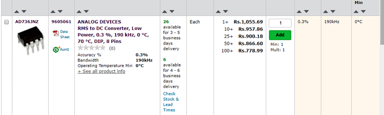
True RMS IC AD736
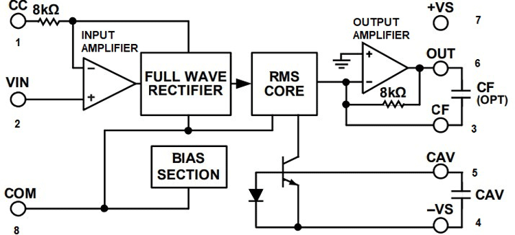
The IC AD736 has few functional subsections like the input amplifier, full-wave rectifier (FWR), RMS core, output amplifier, and bias section. The Input amplifier is constructed with MOSFETs, so it is responsible for the high impedance of this IC.
After the input amplifier, there is a precision full-wave rectifier which is responsible for driving the RMS core. The essential RMS operations of squaring, averaging, and square rooting are performed in the core with the help of an external averaging capacitor CAV. Please note that without CAV, the rectified input signal travels through the core unprocessed.
Finally, an output amplifier buffers the output from the RMS core and allows optional low-pass filtering to be performed via the external capacitor CF, which is connected across the feedback path of the amplifier.
Features of IC AD736
- The features of the IC is listed below
- High input impedance: 10^12 Ω
- Low input bias current: 25 pA maximum
- High accuracy: ±0.3 mV ± 0.3% of reading
- RMS conversion with signal crest factors up to 5
- Wide power supply range: +2.8 V, −3.2 V to ±16.5 V
- Low power: 200 µA maximum supply current
- Buffered voltage output
- No external trims needed for specified accuracy
Note: Please note that the functional block diagram, the functional description, and the features list is taken from the datasheet and modified according to needs.
True RMS to DC Measurements Methods
There are mainly three methods available which DVM’s use to measure AC, they are-
- True-RMS Measurement
- Average Rectified Measurement
- True-RMS AC+DC Measurement
True-RMS Measurement
True-RMS is a pretty common and popular method to measure dynamic signals of all shapes and sizes. In a True-RMS multimeter, the multimeter calculates the RMS value of the input signal and shows the result. This is why it's a very accurate compare to an average rectified measurement method.
Average Rectified Measurement
In an average rectified DVM, it takes the average or the mean value of the input signal and multiplies it by 1.11 and displays the RMS value. So, we can say that it's an average rectified RMS display multimeter.
True-RMS AC+DC Measurement
To overcome the loopholes in a True-RMS multimeter, there exists the True-RMS AC+DC measurement method. If you were to measure a PWM signal with a True-RMS multimeter, you will read the wrong value. Let’s understand this method with some formulas and video, find the video at the end of this tutorial.
Calculation for True RMS converter
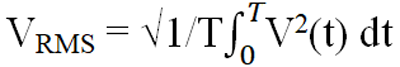
The RMS Value
The formula to calculate RMS value is described as
If we do the calculus by Considering
V(t) = Vm Sin(wt) 0<t<T/2
This boils down to
Vm / (2)1/2
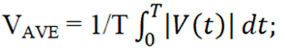
The Average Value
The formula to calculate average value is described as
If we do the calculus by Considering
V(t) = Vm Sin(wt) 0<t<T/2
This boils down to
2Vm / ᴫ
Example Calculation True RMS to DC converter
Example 1
If we consider the peak to peak voltage of 1V and put it in the formula to calculate RMS voltage which is,
VRMS = Vm/√2 = 1/√2 = .707V
Now considering a peak to peak voltage of 1V and putting it in the formula to calculate average voltage which is,
VAVE = 2VM/π = 2*1/π = 2/π = 0.637V
Therefore, in a non-true RMS DVM, the value is calibrated by a factor of 1.11 which comes from VRMS/VAVE = 0.707/637 = 1.11V
Example 2
Now we have a peak to peak pure AC sine wave of 5V and we are directly feeding it to a DVM which has true RMS capabilities, for that the calculation would be,
VRMS = Vm/√2 = 5/√2 = 3.535V
Now we have a peak to peak pure AC sine wave of 5V, and we are directly feeding it to a DVM which is an average rectified DVM, for that the calculation would be,
VAVE = 2VM/π = 2*5/π = 10/π = 3.183V
Now at this point, the value shown in the average DVM is not equal with the RMS DVM, so the manufacturers hard code the 1.11V factor to compensate for the error.
So it becomes,
VAVE = 3.183*1.11 = 3.535V
So, from the above formulas and examples, we can prove that how a non-true RMS multimeter calculates AC voltage.
But this value is only accurate for pure sine waveform. So we can see that we need a true RMS DVM’s to properly measure a non-sinusoidal waveform. Otherwise, we will get an error.
Things to Keep in Mind
Before doing the calculations for the practical application, some facts need to be known to understand the accuracy while measuring RMS voltages with the help of the AD736 IC.
The datasheet of the AD736 tells about the two most important factors that should be taken into account to calculate the percentage of error that this IC will produce while measuring RMS value, they are.
- Frequency Response
- Crest Factor
Frequency Response
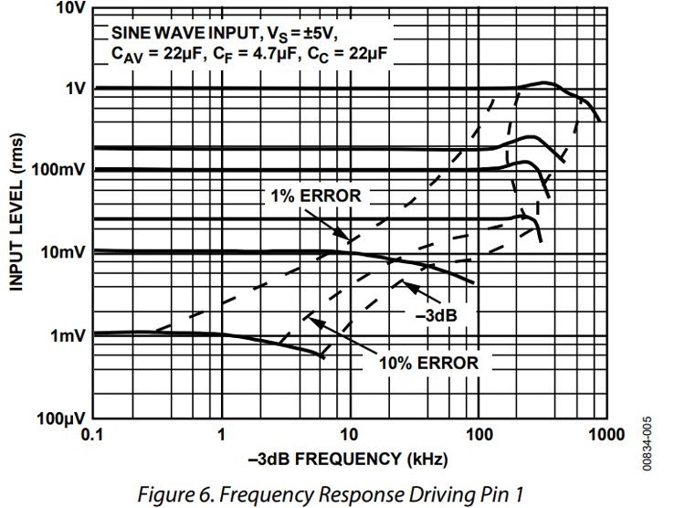
By observing the curves on the graph, we can observe that the frequency response is not constant with amplitude but the lower the amplitude you measure in the input of your converter IC, the frequency response drops, and in the lower measurement ranges at around 1mv, it suddenly drops a few kHz.
The datasheet gives us some figures about this topic which you can see below
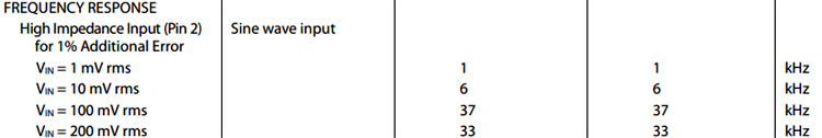
The limit for accurate measurement is 1%
So, we can clearly see that if the input voltage is 1mv and the frequency is 1 kHz, it already reaches the 1% additional error mark. I assume now you can understand the rest values.
NOTE: The frequency response curve and the table are taken from the datasheet.
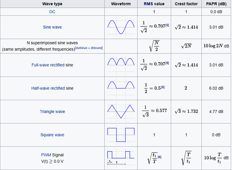
Crest Factor
In simple terms, the crest factor is the ratio of the Peak value divided by the RMS value.
Crest-Factor = VPK/VRMS
For example, if we consider a pure sine wave with an amplitude of
VRMS = 10V
The Peak voltage becomes
VPK= VRMS * √2 = 10*1.414 = 14.14
Now the Crest Factor = 14.14/ 10 = 1.41 (For pure Sine Wave)
You can clearly see that from the below image taken from wikipedia
The table below from the datasheet tells us that if the calculated crest factor is between 1 to 3, we can expect an additional error of 0.7% else we have to consider 2.5% of additional error which is true for a PWM signal.

Schematic for true RMS converter using IC AD736
The below schematic for the RMS converter is taken from the datasheet and modified according to our needs.

Components Required
|
Sl.No |
Parts |
Type |
Quantity |
|
1 |
AD736 |
IC |
1 |
|
2 |
100K |
Resistor |
2 |
|
3 |
10uF |
Capacitor |
2 |
|
4 |
100uF |
Capacitor |
2 |
|
5 |
33uF |
Capacitor |
1 |
|
6 |
9V |
Battery |
1 |
|
7 |
Single Gauge Wire |
Generic |
8 |
|
8 |
Transformer |
0 - 4.5V |
1 |
|
9 |
Arduino Nano |
Generic |
1 |
|
10 |
Breadboard |
Generic |
1 |
True RMS to DC converter- Practical Calculations & Testing
For the demonstration, the following apparatus is used
- Meco 108B+TRMS Multimeter
- Meco 450B+TRMS Multimeter
- Hantek 6022BE Oscilloscope
As shown in the schematic, an input attenuator is used which is basically a voltage divider circuit to attenuate the input signal of the AD736 IC that is because the full-scale input voltage of this IC is 200mV MAX.
Now that we have clear some basic facts about the circuit let us begin the calculations for the practical circuit.
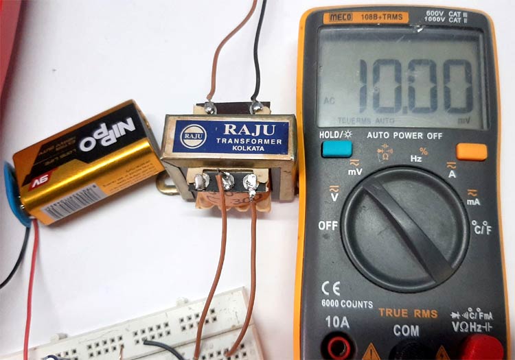
RMS Calculations for 50Hz AC Sine Wave
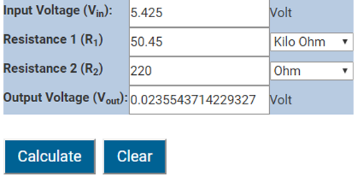
Transformer voltage: 5.481V RMS, 50Hz
Value of Resistor R1: 50.45K
Value of Resistor R1: 220R
Input Voltage of the Transformer
Now if we put these values in an online voltage divider calculator and calculate, we will get the output voltage of 0.02355V OR 23.55mV
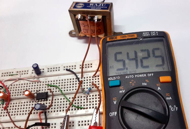
Now the input and the output of the circuit can be clearly seen.
On the right side, the Meco 108B+TRMS multimeter is showing the input voltage. That is the output of the voltage divider circuit.
On the left side, the Meco 450B+TRMS multimeter is showing the output voltage. That is the output voltage from the AD736 IC.
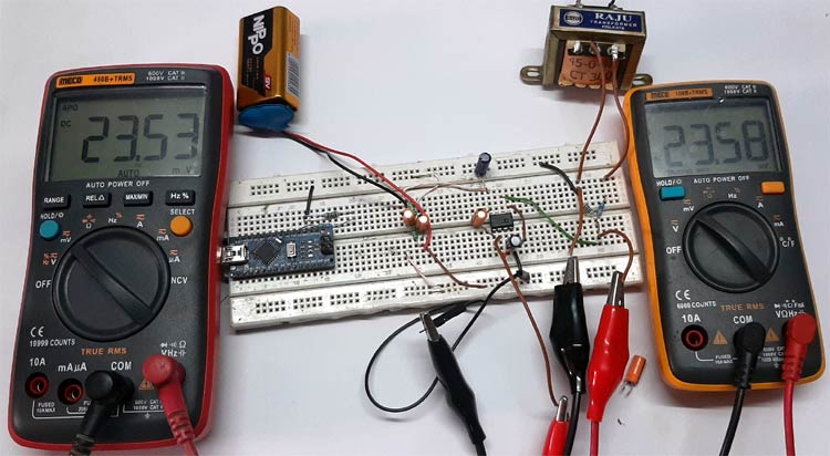
Now you can see that the above theoretical calculation and both the multimeter results are close, so for a pure sine wave, it confirms the theory.
The measurement error in both the multimeter results is due to their tolerance and for demonstration, I am using the mains 230V AC input, which changes very rapidly with time.
If you have any doubts, you can zoom in on the image and see that the Meco 108B+TRMS multimeter is in AC mode and the Meco 450B+TRMS multimeter is in DC mode.
At this point, I did not bother to use my hantek 6022BL oscilloscope because the oscilloscope is pretty much useless and only shows noise at these low voltage levels.
Calculations for PWM Signal
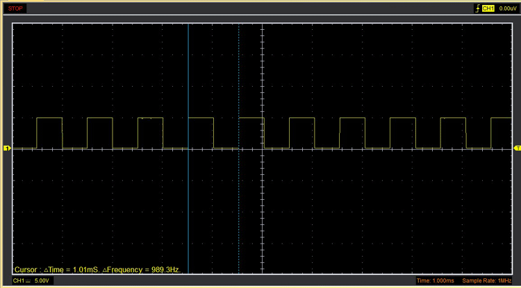
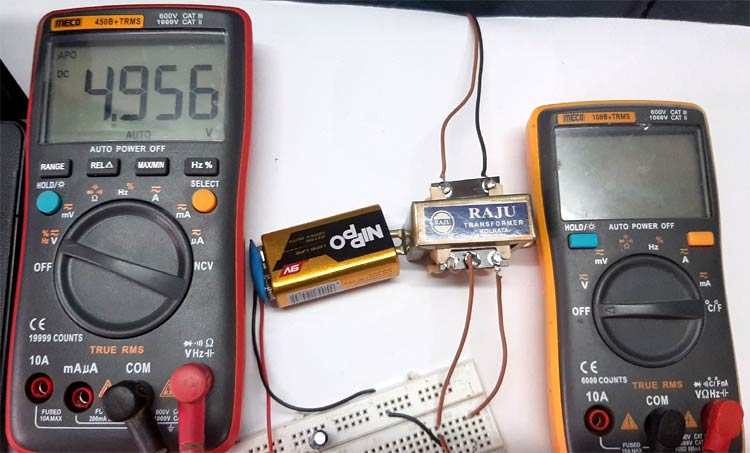
For demonstration, a PWM signal is generated with the help of an Arduino. The voltage of the Arduino board is 4.956V and the frequency is almost 1 kHz.
Max Arduino Board voltage: 4.956V, 989.3Hz
Value of Resistor R1: 50.75K
Value of Resistor R1: 220R
Input Voltage on the Arduino board
Now put these values in an online voltage divider calculator and calculate, we will get the output voltage of 0.02141V OR 21.41mV.

This is the peak voltage of the input PWM signal and to find the RMS voltage, we need to simply divide it by √2 so the calculation becomes
VRMS = Vm/√2 = 0.02141/√2 = 0.01514V or 15.14mV
In theory, a True-RMS multimeter will easily be able to calculate this theoretically calculated value right?
In DC mode
In AC mode
The transformer in the image is sitting there and doing nothing. With that, you can see I am a very lazy person.
So, what is the problem?
Before anybody jumps and says we have done the calculations wrong, let me tell you we have done the calculations right, and the problem is in the multimeters.
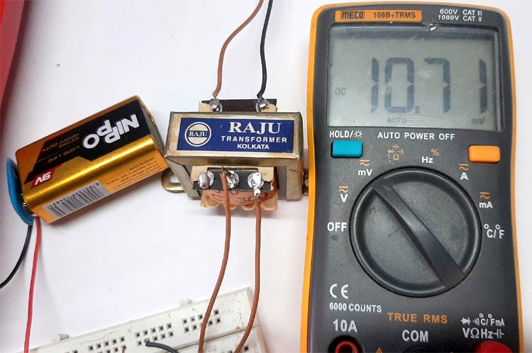
In DC mode the multimeter is simply taking the average of the input signal which we can calculate.
So, the input voltage is 0.02141V and to get the average voltage, it simply multiplies the value by 0.5.
So the calculation becomes,
VAVE = 0.02141 * 0.5 = 0.010705V Or 10.70mV
And that is what we are getting in the multimeter display.
In AC mode, the input capacitor of the multimeter is blocking the DC components of the input signal, so the calculation becomes pretty much the same.
Now as you can clearly see that, in this situation both the readings are absolutely wrong. So, you cannot trust the multimeter display. That is why there exist multimeters with True RMS AC+DC capabilities which can easily measure this kind of waveforms accurately. For example, the extech 570A is a multimeter with True RMS AC+DC capabilities.
The AD736 is a kind of IC that is used to measure these types of input signals accurately. The below image is proof of the theory.
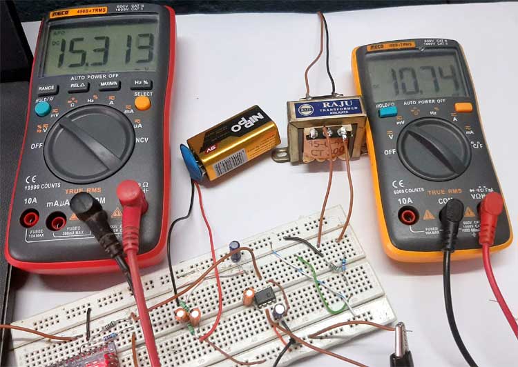
Now we have calculated the RMS voltage to be 15.14mV. But the multimeter shows 15.313mV because we did not consider the crest factor and the frequency response of the AD736 IC.
As we have calculated the crest factor it is 0.7% of the calculated value so if we do the math it boils down to 0.00010598 or 0.10598mV
So,
Vout = 15.14 + 0.10598 = 15.2459mV
Or
Vout = 15.14 - 0.10598 = 15.0340mV
So the value displayed by Meco 450B+ multimeter is clearly within the 0.7% error range
Arduino Code for PWM generation
I almost forgot to mention that I have used this Arduino code to generate the PWM signal with 50% duty cycle.
int OUT_PIN = 2;  // square wave out with 50% duty cycle
void setup()
{
    pinMode(OUT_PIN, OUTPUT);// defining the pin as output
}
void loop()
{
  /*
   * if we convert 500 Microseconds to seconds we will get 0.0005S
   * now if we put it in the formula  F= 1/T
   * we will get F = 1/0.0005 = 2000
   * the pin is on for 500 uS and off for 500 us so the
   * frequency becomes F = 2000/2 = 1000Hz or 1Khz*
   */
  digitalWrite(OUT_PIN, HIGH);
  delayMicroseconds(500);
  digitalWrite(OUT_PIN, LOW);
  delayMicroseconds(500);
}
You can learn more about generating PWM with Arduino here.
Precautions
AD736 True RMS to DC converter IC is by far the most expensive 8-PIN PDIP IC that I have worked with.
After completely destroying one with ESD, I took proper precautions and strapped myself to ground.
Circuit Enhancements
For the demonstration, I have made the circuit in a solderless breadboard which is absolutely not recommended. That is why the measurement error increases after a certain frequency range. This circuit needs a proper PCB with the proper star-ground plane in order to work properly.
Applications of True RMS to DC converter
It is used in
- High precision Voltmeters and multimeters.
- High precision non-sinusoidal voltage measurement.
I hope you liked this article and learned something new out of it. If you have any doubt, you can ask in the comments below or can use our forums for detailed discussion.
A detailed video showing the complete calculation process is given below.

Thank you for your response.