

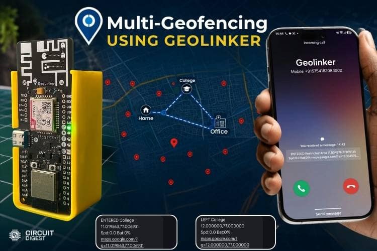
We're all familiar with live GPS tracking; it tells us where a vehicle or device is right now. But what if the system could do more than just show the location? That's where geofencing using IoT comes in. Imagine receiving an instant alert the moment a vehicle leaves home, reaches college, enters the office, or moves into a restricted area. Instead of repeatedly checking a map, the system itself notifies you whenever something important happens. Think about it: if you're tracking a vehicle, do you really want to keep opening the app and checking its location every few minutes? Most of the time, you only care about specific places and important events.
For example, you might want to know when a vehicle reaches college, leaves the office, arrives home, or enters an area that is restricted. Rather than watching the location all day, it would be much easier if the system could automatically inform you whenever these events occur. In this project, we build a complete IoT geofencing system using the GeoLinker GL868_ESP32 board: an ESP32-S3 paired with a SIM868 GSM modem. That's exactly what geofencing helps us do. It allows us to create virtual boundaries around important locations and detect when a device enters or leaves them. By combining geofencing with live GPS tracking, we can build a smarter location-monitoring system that not only tracks a device but also keeps users informed at the right time. Let's dive in and see how to do that. Before that, visit the GeoLinker wikipage to learn about the full spec and get to know the full details of the GeoLinker.
Table of Contents
How Multi-Geofencing Using IoT Works
The system begins by powering on the GeoLinker. Then the board will search for the SIM card and connect to the network, and then keep the board outside for a bit. This ensures the board connects to the satellite for the GPS. Before deploying the code to the board, you should configure multiple geofences by specifying the latitude, longitude, and radius of each zone. In this project, four geofences are created: Home, College, Office, and Restricted Area. Once initialization is complete, the GPS module continuously acquires the current location of the device. The obtained coordinates are then compared with the boundaries of all the configured geofences to determine whether the device is inside or outside each zone.
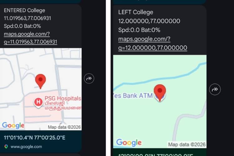
The system continuously monitors the device's movement and checks for any change in geofence status. When the device enters a geofence area, the system detects the event and generates an alert. Similarly, when the device exits a geofence, another alert is generated. For normal zones such as Home, College, and Office, an SMS notification is sent to the registered mobile number whenever an entry or exit event occurs. These alerts help the user know the movement of the tracked device in real time.
A separate geofence is created for the Restricted Area. Whenever the device enters or exits this zone, the system sends an SMS notification and additionally triggers an automatic phone call. The phone call ensures that critical security-related alerts receive immediate attention and are not missed by the user.
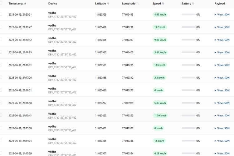
The device periodically uploads its location and signal strength to the CircuitDigest Cloud every 30 seconds, enabling real-time tracking and remote monitoring through the dashboard. This allows the user to view the device's live location and status remotely through the cloud dashboard.
*Note: Not only these, but we also have several example codes like advanced tracking, call triggering, automatic sleep code, etc., which are available in the examples of the Arduino IDE. Spare some time and take a look at those worth exploring if you want to extend this IoT geofencing system project.
Component Requirements for IoT Geofencing System
The components below are the components which are essential ones used to make the geofencing alert system.
| S.No | Components | Purpose | Alternatives |
| 1. | Geolinker Board | GeoLinker GL868_ESP32 is a production-ready, open-source development board that combines an ESP32-S3 and SIM868 GSM modem, used for tracking purposes. | - |
| 2. | IoT / Normal Nano SIM Card | Airtel M2M IoT SIM recommended (3 months free data with board purchase). Any 2G-compatible SIM works. | Regular 2G SIM |
| 3. | 3.7V Li-Ion / LiPo Battery | Used for powering the board | LiPo pouch battery |
| 4. | USB-C Cable | Programming, testing & charging | - |
Hardware Configuration of Geofencing Using IoT
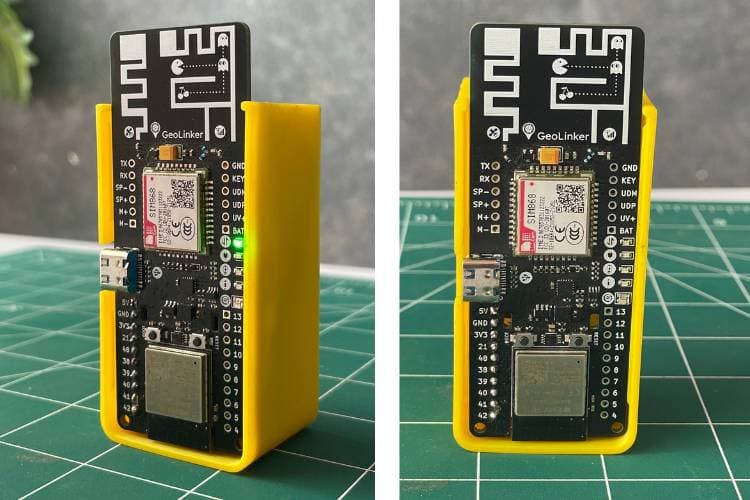
The hardware requirements for this system are minimal. Only the GeoLinker board and a battery are required for operation. The enclosure is optional and is used only for protection and improved appearance. Once the battery is connected to the GeoLinker board, the system automatically powers up and begins the initialisation process.
Code Explanation for the Multi-Geofencing System Using IoT
The code is written with the required libraries for GeoLinker and GPS. It also contains the sections where the coordinates need to be modified to ensure that geofencing works correctly according to the requirements. Different alerts are triggered based on the location. Additionally, the data is sent to the CircuitDigest Cloud at a specified interval.
#define DEVICE_ID            "YourDeviceID"
#define API_KEY              "YourAPIKey"
#define ALERT_NUMBER         "Yournumber"
#define GPS_TIMEOUT          30000UL
#define GPS_MAX_RETRIES      3
#define GPS_POLL_INTERVAL    5000UL
#define CLOUD_SEND_INTERVAL  30
This section contains all the important configuration settings used throughout the program. It defines the device ID, cloud API key, alert phone number, GPS timeout period, polling interval, and cloud upload interval. Keeping these values in one place makes the system easier to configure and maintain without modifying the main logic.
struct GeofenceZone {
const char *name;
double latitude;
double longitude;
double radiusMeters;
bool restricted;
bool insideNow;
};
GeofenceZone zones[] = {
{ "Home", 12.971600, 77.594600, 150.0, false, false },
{ "College", 12.934500, 77.626000, 200.0, false, false },
{ "Office", 12.958000, 77.650000, 200.0, false, false },
{ "Restricted Area", 11.011158, 77.013307, 200.0, true, false },
};
This section defines all the geofences used in the system. Each geofence contains a name, centre coordinates, radius, and alert type. The radius determines the size of the virtual boundary, while the restricted flag specifies whether the zone should generate only SMS alerts or both SMS and phone call alerts. All geofences are stored in an array, allowing the system to monitor multiple zones simultaneously. You should change the long and lat in the GeofenceZone zones[] section in the code for your requirements.
static bool getValidLocation(GPSData *gps) {
for (int retry = 0; retry < GPS_MAX_RETRIES; retry++) {
uint32_t start = millis();
while (millis() - start < GPS_TIMEOUT) {
GeoLinker.update();
if (GeoLinker.getLocationNow(gps) && gps->valid) {
return true;
}
delay(25);
}
}
return false;
}
This function is responsible for obtaining the current GPS location from the GeoLinker module. The system continuously attempts to acquire a valid GPS fix within a specified timeout period. Multiple retries are performed to improve reliability in areas where satellite signals may be weak. Once a valid location is obtained, the coordinates are passed to the geofencing logic for further processing.
double dist = haversineDistance(
  gps->latitude,
  gps->longitude,
  zones[i].latitude,
  zones[i].longitude);
bool nowInside = zones[i].insideNow ?
               (dist <= exitThresh) :
               (dist <= enterThresh);
if (nowInside != zones[i].insideNow) {
  zones[i].insideNow = nowInside;
This section forms the core of the project. The system calculates the distance between the current GPS location and each geofence using the Haversine distance formula. The calculated distance is then compared with the geofence radius to determine whether the device is inside or outside the zone. Whenever the status changes, the system identifies it as an entry or exit event and prepares the corresponding alert.
static void sendGeofenceAlert(
 const char *zoneName,
 bool entered,
 bool restricted,
 GPSData *gps,
 bool hasLoc) {
buildAlertMessage(msg,
                 sizeof(msg),
                 verb,
                 zoneName,
                 gps,
                 hasLoc);
sendReliableSMS(ALERT_NUMBER, msg);
if (restricted) {
 pendingCall = true;
}
}
This function is responsible for generating notifications whenever a geofence event occurs. A detailed alert message containing the event type and location information is first created and sent via SMS. If the geofence is marked as a restricted area, the system additionally schedules a phone call to the registered number.
*Note: A spoof code is also available in the GitHub repository, so you can go through it and test the system while sitting in one place.
Troubleshooting the GPS Geofence Alert System
The following are the problems that were faced while building the system and the different solutions that were used to overcome them. You can take a look at them and use these solutions if you encounter similar problems.
| Problem | Cause | Solution |
| SMS alerts are not received | SIM card not registered on the GSM network or insufficient SMS balance | Check network registration status and ensure the SIM card has sufficient SMS balance and signal strength. |
| Phone call alert is not triggered for the Restricted Area | Incorrect phone number configuration or call service unavailable | Verify the alert phone number in the code and ensure the SIM card supports voice calling. |
| No GPS location is obtained | Weak GPS signal or indoor operation | Move the device outdoors with a clear view of the sky and wait for GPS satellites to lock. |
| Continuous false entry/exit alerts | GPS drift or geofence radius set too small | Increase the geofence radius and ensure GPS accuracy is sufficient for the application |
| System resets unexpectedly | Insufficient power supply during GSM transmission | Use a fully charged 3.7V Li-ion battery capable of supplying peak GSM current requirements |
| Device shows incorrect geofence status after restart | Previous geofence state not stored correctly | Verify NVS memory operation and ensure geofence states are saved properly before power loss. |
| The call is triggered, but not getting sms or vice versa | Maybe your number is not whitelisted. | Make sure to whitelist your registered number for the call and sms too. |
Output Demo of the GPS Tracking System Using IoT
The live tracking of the GeoLinker board is shown below. The board continuously acquires its current GPS coordinates and transmits the location data to the Circuit Digest Cloud at intervals of 30 seconds.
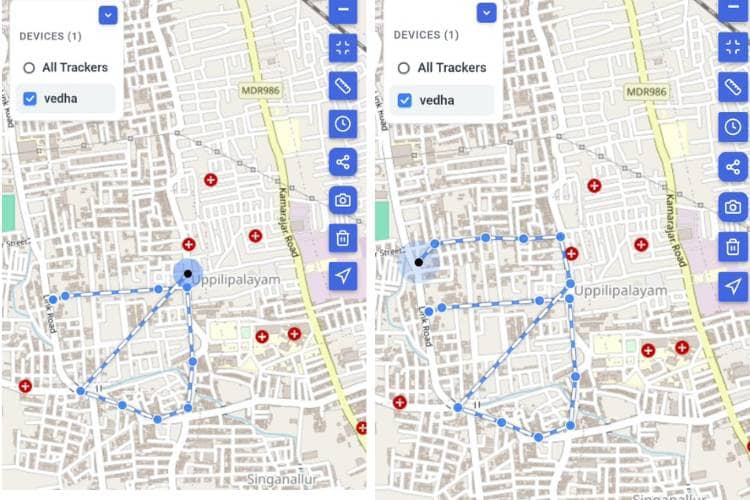
The figure below shows the virtual boundaries (geofences) that have been created for the system. The coordinates corresponding to these geofence areas are defined in the program code that was flashed into the GeoLinker board. These geofences represent specific locations, such as Home, College, Office, and Restricted Areas. Whenever the system enters or exits any of these predefined boundaries, the corresponding alerts are triggered automatically
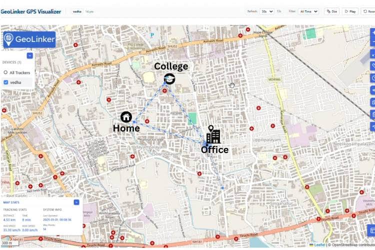
This screen displays the live tracking information received from the GeoLinker board. It includes important parameters such as the current date and time, latitude, longitude, speed, and battery percentage (when a battery is connected to the system). Additionally, the payload section contains further details transmitted by the device, providing comprehensive information about its status and location.
The figure below shows the entry and exit alerts generated for the different geofencing areas. Whenever the device enters or exits a predefined geofence, the system automatically sends an SMS notification to the registered user. The alert message includes the type of event (entry or exit), the name of the geofence area, and the live GPS coordinates of the device at that moment.
Additionally, if the device enters or exits a Restricted Area, the system generates an SMS alert similar to the alerts used for normal geofence zones. However, to ensure that critical notifications are not missed, the system also automatically places a phone call to the registered user. This dual-alert mechanism provides an additional layer of security by immediately drawing the user's attention to important events occurring within restricted zones. As a result, the user is informed through both SMS and voice call notifications whenever the device crosses the boundary of a Restricted Area. We also built an ESP32-based Interactive Voice Response (IVR) System using our GeoLinker board. Take a moment to see how it brings voice interaction and remote connectivity together
Live Working Demo of the Multi-Geofencing IoT System
Watch the Multi-Geofencing System in action as it detects and monitors multiple predefined geographic zones in real time using IoT technology. This live demo showcases accurate location tracking, instant geofence event detection, and seamless system performance.
Applications and Limitations of the Multi-Geofencing System Using IoT
The table below summarises the different applications of the proposed system and its limitations. Understanding these applications helps identify potential use cases, while the limitations provide insight into the factors that may affect the system's performance and reliability.
| S.No | Applications | Limitations |
| 1. | Fleet management for logistics and delivery services | Requires GPS signal availability for accurate location tracking |
| 2. | Monitoring entry and exit of vehicles from homes, offices, and campuses | GPS performance may be affected in tunnels, underground areas, or dense urban environments |
| 3. | Personal vehicle safety and anti-theft monitoring | SMS and call delivery may be delayed if network connectivity is poor |
| 4. | Real-time location-based notification systems | Continuous GPS and GSM operation increases power consumption |
| 5. | Restricted area monitoring and security applications | Requires periodic maintenance of the SIM card and data services |
Conclusion for the IoT Geofencing System Project
In conclusion, this project shows how GPS tracking can be made more useful by adding geofencing capabilities. Instead of simply displaying the current location of a device, the system is able to recognise important location-based events and notify the user automatically. By creating multiple virtual boundaries and monitoring them continuously, this multi-geofencing system using IoT can detect when a device enters or exits specific zones and respond immediately. This system demonstrates the effective integration of GPS, GSM, cloud connectivity, and geofencing into a single system. It also highlights how automated alerts can reduce the need for constant manual monitoring. We also did an interesting project on parcel tracking. Feel free to check out our How to Build a Smart Parcel Tracking System Using IoT project.
IoT Geofencing System GitHub
Download the complete source code, circuit schematics, and project files to build your own IoT-based Multi-Geofencing System.


Frequently Asked Questions
⇥ How does the system know when a device enters or leaves a zone?
The GPS location of the device is continuously compared with the coordinates and radius of each geofence. When the device crosses the boundary, an entry or exit event is detected.
⇥ Why is geofencing useful?
Geofencing helps users receive automatic notifications based on location events instead of constantly checking the device's location on a map.
⇥ What happens when a geofence is crossed?
The system automatically generates alerts. In this project, SMS notifications are sent for normal zones, while SMS and phone call alerts are generated for restricted areas.
⇥ Why is a phone call used in the restricted area?
A phone call provides immediate attention and reduces the chance of missing an important security-related alert.
⇥ Can multiple geofences be created?
Yes. The system supports multiple geofences such as Home, College, Office, and Restricted Area, and can monitor all of them simultaneously.
⇥ What technology is used to determine the location?
The system uses GPS technology to obtain the real-time location of the device.
⇥ How often is location data uploaded to the cloud?
The device uploads location data to the cloud every 30 seconds under normal operating conditions.
Related Raspberry Pi AI Projects Using CircuitDigest Cloud
Looking for more Raspberry Pi AI projects? Explore our CircuitDigest Cloud tutorials on Face Detection, Object Detection, and Helmet Detection. Each project includes detailed instructions, source code, hardware setup, and cloud-based AI implementation.

How to Build a Face Detection System Using a Raspberry Pi and CircuitDigest Cloud
This project is based on the same concept, in which we have built a Raspberry Pi face detection system without any complex setup. We only need a Raspberry Pi, a USB camera, and an account in CircuitDigest Cloud.

How to do Object Detection with Raspberry Pi Using CircuitDigest Cloud
That is exactly what this Raspberry Pi object detection project demonstrates. You can build a fully working object detection system on a Raspberry Pi without collecting a dataset, labelling images, or training any machine learning model.
How to Build Helmet Detection with Raspberry Pi Using CircuitDigest Cloud
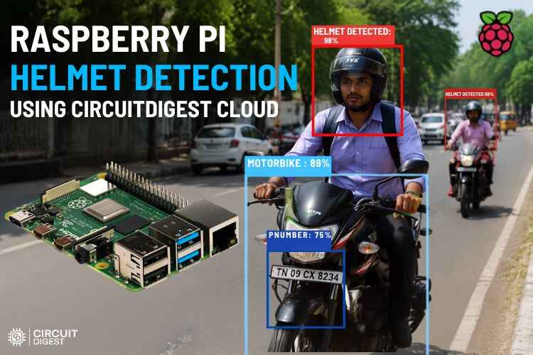
So, what if there were a compact system that could make this task easier, provide accurate results, and reduce the burden on traffic police? That's exactly what this system does; here we used the Raspberry Pi, a powerful controller that can process data, analyse the images, and give the results instantly.

Add a comment
No account needed. Your comment appears once a moderator has reviewed it.