 Vedhathiri
Author
Imagine you've just sent a parcel through a courier service. As soon as it leaves your hands, you start wondering what is happening to it. Is it being handled carefully? Has it been dropped or damaged? Is it still on the right route? Will it reach the destination safely and on time? The truth is, once we send a parcel, we have very little idea about what happens during its journey. All we can do is wait and hope that it arrives in good condition. But with today's technology, do we really have to depend only on hope? What if you could know where your parcel is at any time, find out if it was handled roughly, and receive an alert if something goes wrong? That's exactly the idea behind this real-time parcel tracking system. In this project, we built a smart parcel tracking system using the GeoLinker board that continuously tracks the parcel's location, detects shocks and vibrations using an onboard accelerometer, uploads real-time data to the cloud, and instantly notifies the owner through SMS whenever a severe impact is detected. This guide walks you through the complete process of building a parcel tracking system using GPS and IoT from scratch. Before we begin, take a few minutes to explore our GeoLinker Wiki page to get a better understanding of the board, its features, and specifications. It will help you follow the project much more easily. Also check out our website to get more ideas about IOT projects
Table of Contents
Components Required for Parcel Tracking Using IoT
Building an IoT parcel tracking system requires very few components. The components below are the essential ones that are used to make the parcel monitoring system.
| S.No | Components | Purpose | Alternatives |
| 1. | Geolinker Board | GeoLinker GL868_ESP32 is a production-ready, open-source development board that combines an ESP32-S3 and SIM868 GSM modem, used for tracking purposes | - |
| 2. | IoT / Normal Nano SIM Card | Airtel M2M IoT SIM recommended (3 months free data with board purchase). Any 2G-compatible SIM works. | Regular 2G SIM |
| 3. | 3.7V Li-Ion / LiPo Battery | Used for powering the board and testing | - |
| 4. | USB-C Cable | Programming, testing & charging | - |
Hardware Connection of Real-Time Parcel Tracking System
The hardware setup for this real-time parcel tracking system is minimal. Only the GeoLinker board and a battery are required for operation. The enclosure is optional and is used only for protection and improved appearance. Once the battery is connected to the GeoLinker board, the system automatically powers up and begins the initialisation process.
How the Parcel Monitoring System Works
Data Acquisition and Impact Detection
After powering on, the ESP32 initialises the GeoLinker board, GPS module, GSM/GPRS connectivity, battery monitoring system, and the onboard LIS3DHTR accelerometer. The accelerometer performs baseline calibration and continuously measures acceleration along all three axes. Whenever the measured acceleration exceeds the predefined threshold, the system detects an impact, classifies it as a vibration, jerk, or jump, updates the impact counters, and records the event the core of how this IoT package tracking project senses rough handling.
Location Tracking and Alert Generation
The GPS module continuously acquires the parcel's location, enabling true live parcel tracking using IoT throughout transportation. If a detected impact exceeds the severe impact threshold, the system immediately generates an SMS alert containing the impact value, battery status, ride duration, and GPS coordinates. This ensures that critical handling incidents are reported instantly to the registered user for immediate attention.
Cloud Monitoring and Data Logging
Every 30 seconds, the system prepares a JSON payload containing:
- GPS coordinates
- Total impact count
- Peak impact value
- Vibration count
- Jerk count
- Jump count
- Ride duration
- Battery percentage
This information is uploaded to the CircuitDigest Cloud using the GPRS connection for real-time monitoring and analysis. In addition, a summary SMS containing shipment statistics, battery status, ride duration, and location details is automatically sent every 30 minutes to provide periodic updates about the shipment condition. Not only this feature, but we have done a project related to geofencing, spare some time and check out our Build a GPS Tracker with Seeed Studio XIAO ESP32-S3 and Geofencing project.
Code Explanation for Real-time Parcel Tracking System
The code begins by including all the required libraries for GPS, GSM/GPRS, SMS, sensor communication, and other essential functions. Next, the necessary project credentials, such as the device ID, API key, alert number, and impact thresholds, are configured. The system then initializes the GeoLinker board and establishes communication with the GPS and GSM modules. Finally, the GPRS connection, SMS service, and onboard sensors are initialized, making the system ready for real-time tracking, cloud communication, and alert generation.
#define DEVICE_ID "Device_ID"
#define API_KEY "YOURAPIKEY"
#define ALERT_NUMBER “YOURNUMBER"
#define IMPACT_THRESHOLD_MG 600.0f
#define SEVERE_IMPACT_MG 4000.0f
GeoLinker.begin(DEVICE_ID, API_KEY);
GeoLinker.setOperatingMode(MODE_SMS_CALL);
GeoLinker.setTimeOffset(5, 30);
GeoLinker.enableFullPowerOff(false);
This section initializes the entire system and defines all important project parameters. The device ID and API key establish communication with the GeoLinker cloud platform, while the alert number is used for sending SMS notifications. Impact thresholds determine the minimum acceleration required to register an impact and the level at which a severe impact alert is generated
static bool accelInit() {
Wire.begin();
Wire.beginTransmission(LIS3DH_ADDR);
Wire.write(LIS3DH_CTRL_REG1);
Wire.write(0x57);
Wire.endTransmission();
Wire.beginTransmission(LIS3DH_ADDR);
Wire.write(LIS3DH_CTRL_REG4);
Wire.write(0x10);
Wire.endTransmission();
return true;
}
float dynamicMg = accelMagnitude(ax, ay, az);
if (dynamicMg > IMPACT_THRESHOLD_MG) {
impactCount++;
impactsSinceLastPush++;
}
This section is responsible for detecting shocks and vibrations experienced by the package. The LIS3DHTR accelerometer is configured through I2C communication and continuously measures acceleration along the X, Y, and Z axes. After initialization, the system calculates the dynamic acceleration by removing the effect of gravity using baseline calibration.
static ImpactBand classifyImpact(float mg) {
if (mg < BAND_VIBRATION_MAX)
 return BAND_VIBRATION;
if (mg <= BAND_JERK_MAX)
 return BAND_JERK;
return BAND_JUMP;
}
if (dynamicMg > SEVERE_IMPACT_MG && !severeAlertSent) {
 severeAlertSent = true;
 sendSevereImpactAlert(dynamicMg, &alertGPS, hasEverHadFix);
}
Once an impact is detected, the system categorizes it into Vibration, Jerk, or Jump based on its magnitude. This classification helps analyze how rough the transportation conditions are. The project also continuously monitors for severe impacts. If a single impact exceeds the severe threshold of 4000 mg, an emergency SMS alert is immediately sent to the registered mobile number
if (GeoLinker.getLocationNow(gps) && gps->valid) {
  Serial.printf("[GPS] Fix: %.6f, %.6f\n",
                gps->latitude,
                gps->longitude);
  return true;
}
lastKnownGPS = gps;
hasEverHadFix = true;
The GPS module continuously acquires the geographical location of the shipment. The code repeatedly checks whether a valid GPS fix has been obtained and stores latitude and longitude coordinates whenever available, forming the backbone of the parcel tracking system using GPS and IoT. These coordinates are used to track the package in real time and identify locations where impacts occur.
GeoLinker.setPayloads({
{"impacts", (float)impactCount},
{"peak_mg", peakImpact},
{"ride_min", (float)rideMinutes},
{"vib_count", (float)bandCount[BAND_VIBRATION]},
{"jerk_count", (float)bandCount[BAND_JERK]},
{"jump_count", (float)bandCount[BAND_JUMP]}
});
int code = GeoLinker.gsm.httpPOST(
  "http://www.circuitdigest.cloud/api/v1/geolinker",
  API_KEY,
  "application/json",
  payload);
This section handles communication and data storage. Every 30 seconds, the system creates a JSON payload containing GPS coordinates, impact statistics, battery percentage, ride duration, and impact classifications. This information is uploaded to the CircuitDigest cloud platform using a GPRS connection, enabling remote monitoring.
Troubleshooting of the IoT Parcel Tracking System
The following are the problems that were faced while building the system and the different solutions that were used to overcome them. You can take a look at them and use these solutions if you encounter similar problems.
| Problem Encountered | Possible Cause | Solution |
| Impacts are not being detected | The LIS3DHTR accelerometer may not be communicating properly through I2C, or the configured impact threshold may be too high for the vibration levels being experienced. | Verify that the accelerometer initializes successfully during startup and monitor raw acceleration values through Serial Monitor. |
| GPS location is not updating | The GPS module may not have a clear view of the sky, resulting in weak satellite reception. | Place the device outdoors in an open area and allow sufficient time for satellite acquisition before beginning monitoring. |
| GPS coordinates appear inaccurate | Satellite signal reflections, obstructions, or insufficient satellites can reduce positioning accuracy. | Ensure operation in an open area and wait for additional satellites to improve GPS precision before relying on location data. |
| Device restarts unexpectedly | Power supply fluctuations, low battery voltage, or excessive current draw may cause system resets | Use a stable power source, ensure adequate battery capacity, and verify all power connections. |
| Battery percentage readings appear incorrect | Battery calibration settings may not match the actual battery characteristics. | Verify battery voltage measurements and adjust battery range configuration if necessary. |
| GPRS connection fails after SMS transmission | The GSM modem may not successfully reattach to the GPRS network after sending an SMS | Verify the GPRS reattachment process and ensure the modem reconnects before attempting cloud uploads. |
Output Demonstration of the Live Parcel Tracking Using IoT
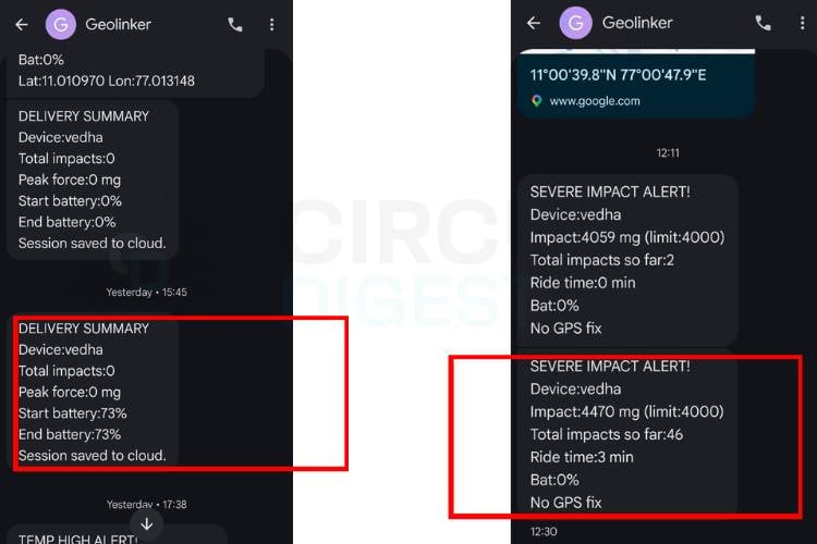
The image below shows the SMS alerts generated by the system. The first message notifies the user about an impact detected on the parcel, including the impact level and the time of occurrence. The second message is a 30-minute summary report, providing an overview of the parcel's condition during the monitoring period, including the total number of impacts detected and other relevant status information.
This shows the live tracking of the parcel. The system uploads data to the cloud every 30 seconds, allowing users to monitor the parcel's current location in real time. It also records and displays vibrations, jerks, jumps, and severe impacts at every waypoint throughout the journey, providing a complete overview of the parcel's handling and movement.
With this, our Smart Parcel Monitoring System is complete. The project demonstrates how the GeoLinker GL868 ESP32 board can be used to build a reliable solution for a parcel tracking system using GPS and IoT, detecting rough handling, and providing real-time updates through cloud monitoring and SMS alerts. Although this prototype focuses on parcel monitoring, the same concept can be extended to logistics, fleet management, asset tracking, and many other IoT applications. We hope this guide helps you build your own IoT package tracking project and inspires you to create even more innovative projects using the GeoLinker platform.
Secure Smart Parcel System Using IoT - Live Working Demo
Watch the IoT-powered Smart Parcel System in action, showcasing secure package delivery with real-time monitoring and automated notifications. Experience how IoT technology enhances parcel safety, tracking accuracy, and delivery efficiency through a live working demonstration.
IoT Parcel Tracking System GitHub
Access the complete source code, documentation, and project files for the IoT Parcel Tracking System on GitHub. Explore the implementation, customise the project, and contribute to its further development.


Frequently Asked Questions
⇥ How does the system detect impacts?
The built-in LIS3DHTR accelerometer continuously measures acceleration. When the measured acceleration exceeds a predefined threshold, the system identifies it as an impact event.
⇥ Why is an accelerometer used in this project?
The accelerometer helps detect shocks, jerks, vibrations, and sudden movements that may occur while transporting fragile packages.
⇥ What is the impact threshold used in the system?
The system is configured to detect impacts above 600 mg. Any acceleration above this value is considered a valid impact.
⇥ How are impacts classified?
Impacts are classified into three categories: Vibration, Jerk, and Jump, based on the measured acceleration magnitude.
⇥ What is considered a severe impact?
A severe impact is any single impact exceeding 4000 mg. Such events may indicate rough handling or possible damage to the package.
⇥ What happens when a severe impact is detected?
The system immediately sends an SMS alert to the registered mobile number, notifying the user about the severe impact event
⇥ What is the purpose of the 30-minute summary SMS?
The summary SMS provides a periodic report containing impact statistics, battery status, ride duration, and the current location of the shipment.
Featured GPS Tracker Projects
Explore practical GPS tracker implementations using Raspberry Pi Pico, Arduino, and A9G development boards. Each project demonstrates efficient location tracking and wireless data transmission techniques.
Build a Real-Time GPS Tracker with Raspberry Pi Pico & SIM800L GSM Module
This comprehensive Raspberry Pi Pico GPS tracker tutorial demonstrates how to create a professional-grade IoT tracking device using the SIM800L GSM module, Neo 6M GPS module with Raspberry Pi, and the versatile Raspberry Pi Pico microcontroller.
Arduino Location Tracker using SIM800L GSM Module and NEO-6M GPS Module
This comprehensive project shows you how to create a fully functional GPS tracking system using Arduino UNO R3, SIM800L GSM module, and NEO-6M GPS module, a perfect low-cost DIY combination for vehicle monitoring, asset protection, or personal safety applications.
Build A Low Power SMS Based Vehicle Tracking System with A9G GSM+GPS Module and Arduino
So, in this tutorial, we decided to take a deep dive into the technical specs of this module and find out all its hidden features. Also, we will be building an SMS-based GPS tracker that will be able to update the position of the device with an SMS containing all the GPS location data.
