 Anand D
Author

Bluetooth communication is everywhere. Due to its low power consumption, we can see it in a lot of our day-to-day gadgets. Behind the scenes, it's all about signals. Let’s explore what really happens when data is transmitted or disturbed via Bluetooth. This project is based on an ESP32 and two NRF24L01 modules, and we are going to learn how we can generate a 2.4 GHz spectrum signal and interrupt Bluetooth communications. This blog is meant for educational purposes only. By using two RF modules, each controlled independently via the ESP32’s HSPI and VSPI interfaces, the system can generate parallel data packets across multiple channels. If you are a beginner and would like to learn beginner-friendly steps of interfacing the NRF24L01 module with an Arduino, do check out our NRF24L01 with Arduino project, which is a great starting point before diving into this more advanced Bluetooth jammer using an ESP32 build. Using an ESP32 and two NRF24L01 + PA + LNA modules, we built a dual ESP32 Bluetooth jammer capable of generating wideband 2.4 GHz spectrum interference to study wireless disruption in a controlled, educational setting.
Here, the ESP32 acts as the central controller, coordinating rapid data transmissions between the two NRF24L01 modules, while the rest of the components support system operation and monitoring. If you follow this tutorial completely, you’ll get valuable insights into wireless communication, ideas on signal generation and transmission, IoT systems and real-world signal challenges. Interested in more ESP32 hands-on builds? Explore our ESP32 projects.
What You Learn From The ESP32 Bluetooth Jammer Project
- Wireless protocol fundamentals
- 2.4 GHz RF interference
- Dual SPI bus operation
- NRF24L01 PA+LNA operation
- IoT system challenges
- Firmware deployment
Table of Contents
- What Is Bluetooth and How Does It Work?
- How Frequency Hopping Spread Spectrum (FHSS) Works
- How Does a Bluetooth Jammer Using ESP32 Work?
- Why Use Two NRF24L01 Modules? (Dual ESP32 Bluetooth Jammer Design)
- Components Required
- Circuit Diagram
- Pin Connection Table
- Hardware Assembly
- Flashing Firmware
- Video Demonstration
- Understanding HSPI and VSPI on the ESP32
- Common Issues and Troubleshooting
What Is Bluetooth and How Does It Work?
Bluetooth is a short-range wireless communication technology that has become the universal standard for connecting personal devices without any cables. Named after a 10th-century Danish king, the technology was developed in the late 1990s to allow phones, computers, and peripherals to "talk" to one another seamlessly. It operates in the 2.4 GHz ISM (Industrial, Scientific, and Medical) band, the same unlicensed frequency range used by Wi-Fi and microwave ovens, which makes it globally accessible for consumer electronics. Today, Bluetooth is divided into two main categories: Bluetooth Classic, used for high-throughput tasks like streaming high-fidelity audio to headphones, and Bluetooth Low Energy (BLE), designed for power-sensitive applications like fitness trackers and smart home sensors. Because it is managed by the Bluetooth Special Interest Group (SIG), devices from thousands of different manufacturers can interoperate, ensuring that your smartphone can connect to almost any car, speaker, or smartwatch on the market, regardless of the brand.
There are two primary types of Bluetooth today:
Bluetooth Classic is utilised for streaming music, etc., typically to a headset or speaker, i.e. "high bandwidth" activity using 79 channels around 2.45 GHz and 1600 times per second on the same channel (frequency hopping).
Bluetooth Low Energy (BLE) is mainly used for low-power Internet of Things (IoT) devices such as fitness trackers, smart home sensors, and beacons and provides for all connections via 40 channels via a method called "adaptive frequency hopping".
Because Bluetooth has been developed and enforced by a consortium known as the Bluetooth Special Interest Group (SIG), devices produced by different manufacturers can communicate with one another, meaning that you will be able to set up a pairing system with almost any car, speaker or smart watch regardless of the manufacturer.
Quick Answer: What does this ESP32 Bluetooth jammer project do?
It uses an ESP32 controlling two NRF24L01 PA+LNA radio modules (one on HSPI, one on VSPI) to simultaneously broadcast RF noise across the 2.4 GHz band. This floods the channels Bluetooth relies on, causing packet loss and connection instability in nearby devices, demonstrating FHSS vulnerability in a controlled educational experiment.
How Frequency Hopping Spread Spectrum (FHSS) Works
At its core, Bluetooth functions through a process called Frequency Hopping Spread Spectrum (FHSS). To avoid interference from other wireless devices, a Bluetooth connection doesn't stay on one frequency; instead, it "hops" between 79 different channels (for Classic) or 40 channels (for BLE) up to 1,600 times per second. When two devices connect, they form a "Piconet" where one device acts as the central (or master) and the others act as peripherals (or slaves), following a synchronized hopping pattern that only they know. If you’d like to see how a smartphone can interact with an ESP32 as a client device, dive into our ESP32 Bluetooth iBeacon project. When you "pair" devices, they exchange unique addresses and security keys to establish a trusted bond. Once the link is active, data is broken into small packets and sent across the changing frequencies. If a packet is lost due to noise on one channel, the devices simply retransmit the data on the next hop. This agility is what allows dozens of Bluetooth devices to operate in the same room without crashing into each other's signals.
| Parameter | Bluetooth Classic | Bluetooth Low Energy (BLE) |
| Frequency Band | 2.4 GHz ISM | 2.4 GHz ISM |
| Number of Channels | 79 channels (1 MHz spacing) | 40 channels (2 MHz spacing) |
| Max Hop Rate | 1,600 hops/second | Adaptive (connection interval-based) |
| Max Data Rate | 3 Mbps (EDR) | 2 Mbps (BLE 5.0) |
| Typical Range | 10–100 m | 10–400 m (BLE 5.0 Long Range) |
| Power Consumption | Higher (~1–3 W peak) | Very low (~15 mW peak) |
| Primary Use Cases | Audio streaming, file transfer | IoT sensors, beacons, wearables |
| Interference Method | Flood 79 channels with RF noise | Flood 40 advertising/data channels |
How Does a Bluetooth Jammer Using ESP32 Work?
Bluetooth jammers work by exploiting the fact that every wireless receiver has a limit on how much "noise" it can filter out. A jammer typically functions as a powerful radio frequency (RF) transmitter that floods the 2.4 GHz band with useless, high-intensity energy. By blasting "white noise" or a continuous carrier wave across the same channels Bluetooth uses, the jammer raises the noise floor so high that the legitimate Bluetooth signal becomes drowned out - much like trying to have a whisper-quiet conversation in the front row of a heavy metal concert.
In our project, we have two NRF24L01 + PA + LNA modules connected to our ESP32 board. You can explore our beginner-friendly interfacing of the NRF24L01 with Arduino UNO tutorial for in-depth insights into the NRF modules. The need for two NRF modules here is to increase the range of our ESP32 Bluetooth jammer. Each of the NRF modules is connected to two SPI buses (HSPI and VSPI) of the ESP32. Each NRF24L01 operates in the same 2.4 GHz band and can transmit data on different channels. Both modules rapidly transmit signals. Each one can operate on different channels. Together, they increase activity across the spectrum. When the air becomes crowded with these signals, packet loss increases, connections may become unstable, and there will be interruptions in the Bluetooth communication of nearby devices. I have attached a 1000mAh LiPo battery to power the device, but you can use a power bank and connect it to the USB port of the ESP32 to power the device on.
Why Use Two NRF24L01 Modules? (Dual ESP32 Bluetooth Jammer Design)
An NRF24L01 is limited to transmitting on a single channel; even though it can rapidly hop between channels on the 2.4 GHz band, this presents a varying gap of transmission when using just one transceiver.
In this dual ESP32 Bluetooth jammer design, two NRF24L01 + PA + LNA modules are operated in parallel across the ESP32's independent HSPI and VSPI buses.
This allows:
» Transmit simultaneously across more channels at once.
» Have a greater density of spectral coverage; thus, fewer unpopulated parts of the frequency will be present.
» Having a greater effective jamming distance is caused by the amplification from the PA (Power Amplifier).
» Enable independent channel mapping, which increases the chance of evenly flooding the entire band.
With both transceivers transmitting at the same time on their assigned channels, packet loss will increase significantly, connections will be disrupted, and streams (audio or data) will stutter or be dropped. The Power Amplifier (PA) increases the transmission power output of the transmitter, which increases its effective distance; whereas, the Low Noise Amplifier (LNA) allows the module to accurately identify active channels before flooding those channels with noise.
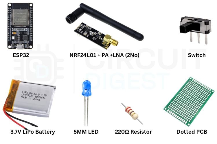
Components Required to Build the ESP32 Bluetooth Jammer
The following is the list of components required to build the ESP32 Bluetooth jammer
| S No | Item | Quantity | Description |
| 1 | ESP32 | 1 | Acts as the central controller of the whole circuit |
| 2 | NRF24LO1 + PA + LNA | 2 | To transmit the radio signals |
| 3 | Switch | 1 | To turn on and off the circuit |
| 4 | 3.7V LiPo battery | 1 | To power up the circuit |
| 5 | 5mm LED | 1 | Status indicator for the ESP32 Bluetooth jammer |
| 6 | 220Ω Resistor | 1 | To limit the current going to the LED |
| 7 | Dotted PCB | 1 | To assemble the whole circuit |
Circuit Diagram – ESP32 Bluetooth Jammer with Dual NRF24L01
You can follow the following circuit diagram to build your own ESP32 NRF24L01 Bluetooth jammer.
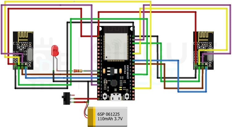
In this project, we have used two NRF24L01 + PA + LNA modules. The NRF modules are connected to two SPI buses (HSPI and VSPI) of the ESP32. ESP32 acts as the "Master" controlling two "Slave" radio modules. The pin connections can be seen in the pin connections table. Power management is the most critical aspect of this specific circuit, especially when using the PA+LNA versions of the NRF24L01. The Power Amplifier boosts the outgoing signal, while the Low Noise Amplifier allows the device to better "hear" and target specific active channels before flooding them with interference.
We have used a dedicated 3.7V, 1000mAh LiPo battery to power the whole circuit. You can also use a power bank to power the circuit, just connect the ESP32 to the power bank using USB. A 10uF electrolytic decoupling capacitor soldered directly across the VCC and GND pins of each NRF module acts as a local reservoir of energy, smoothing out voltage drops and ensuring the radio has enough "punch" to transmit across the 2.4GHz band effectively. An LED is connected to GPIO 27 via a 220Ω resistor to see the status of the ESP32 NRF24L01 Bluetooth jammer. The Toggle button connected between the battery and the circuit helps us to turn on and off the device when required. I have assembled all the components in a dotted PCB. You can design a custom PCB if you like it to be more professional. If you want to learn how to send data to a smartphone using Arduino and NRF24L01, check out our sending data to a smartphone using NRF24L01 over Bluetooth tutorial!
Pin Connection Table – ESP32 NRF24L01 Bluetooth Jammer
You can follow the following pin connections. These pin connections will work for any ESP32 boards, provided that they have the mentioned pins.
| LEFT NRF CONNECTION (HSPI) | RIGHT NRF CONNECTION (VSPI) | ||
| VCC | 3.3V | VCC | 3.3V |
| GND | GND | GND | GND |
| CE | GPIO 16 | CE | GPIO 22 |
| CSN | GPIO 15 | CSN | GPIO 21 |
| SCK | GPIO 14 | SCK | GPIO 18 |
| MOSI | GPIO 13 | MOSI | GPIO 23 |
| MISO | GPIO 12 | MISO | GPIO 19 |
| IRQ | — | IRQ | — |
| STATUS LED CONNECTION | SWITCH CONNECTION | ||
| POSITIVE | GPIO 27 | PIN 1 | BATTERY + |
| NEGATIVE | GND | PIN 2 | ESP32 - 5V PIN |
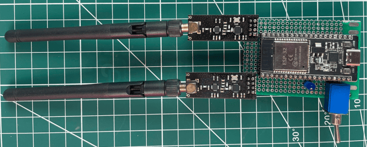
Hardware Assembly – Full ESP32 Bluetooth Jammer Build
The following is the complete picture of the Bluetooth jammer after assembling all of the parts. You can either connect a powerbank to the USB Type-C port of the ESP32 or just connect a 3.7V battery to the 5VIN pin of the ESP32, as I did.
Flashing the Bluetooth Jammer Firmware to ESP32
We are using the Bluetooth Jammer firmware developed by Emensta Noughat. To flash the firmware, go to the bluetooth jammer firmware flasher page and follow the steps described below.
Step 1 ⇒ Select the Correct Firmware
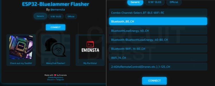
After going to the link, click Generic. Make sure your ESP32 device is plugged into your PC via USB connection. A menu with a list of firmwares will pop up. Click Bluetooth_80_CH and click CONNECT.
Step 2 ⇒ Connect Your ESP32 and Install
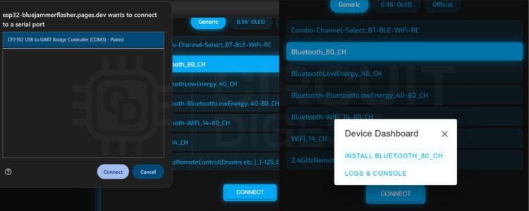
A new pop-up window with a list of available ESP32 devices with their COM ports will be shown. Choose your ESP32 device from the list and click connect. You need to click INSTALL BLUETOOTH_80_CH from the options displayed.
Step 3 ⇒ Confirm Successful Flash
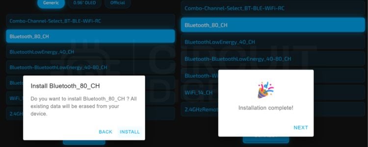
Again, click Install. If it shows, you may want to press the BOOT button on your ESP32 if it shows “Failed to initialise”. Firmware will start flashing into the ESP32. You will see the following on successful firmware flash. The ESP32 Bluetooth jammer is active and transmitting RF noise across all 80 channels.
Video Demonstration – ESP32 NRF24L01 Bluetooth Jammer in Action
In this video, I’ve clearly demonstrated how our device disturbs the Bluetooth communication between a phone and a Bluetooth speaker. Initially, the Bluetooth speaker works fine, and the song gets played seamlessly. The moment I turn on the ESP32 NRF24L01 Bluetooth jammer, the song being played gets disrupted and stops. What actually happened is we filled the air around the speaker and the phone with a lot of noise, and the Bluetooth devices failed to establish a proper communication channel between them.
Understanding HSPI and VSPI on the ESP32
This dual ESP32 Bluetooth jammer design takes advantage of the unique dual architecture of the ESP32's SPI controllers, as well as the fact that ESP32 modules have their own communication lines. The majority of microcontrollers contain only one hardware SPI controller; in contrast, the ESP32 has two totally independent hardware SPI peripherals.
| Property | HSPI (SPI2) | VSPI (SPI3) |
| Default SCK Pin | GPIO 14 | GPIO 18 |
| Default MOSI Pin | GPIO 13 | GPIO 23 |
| Default MISO Pin | GPIO 12 | GPIO 19 |
| Max Clock Speed | 80 MHz | 80 MHz |
| DMA Support | Yes | Yes |
| In This Project | Left NRF24L01 module | Right NRF24L01 module |
The ESP32 firmware can operate both modules separately by assigning an NRF24L01 to each SPI. The ESP32 will access both NRF24L01 modules at the same time, which means that using two NRF24L01 devices with the ESP32 provides coverage of multiple channels at the same time and therefore makes the Bluetooth jammer more effective than a single device would.
The RF24 library abstracts out both SPI interfaces and allows the firmware to switch back and forth between the two NRF24L01 devices at a high speed.
Common Issues and Troubleshooting
| Symptom | Likely Cause | Fix |
| The status LED does not light up | Firmware not flashed, or LED polarity reversed | Re-flash firmware; verify LED anode connects to GPIO 27 via 220Ω resistor |
| "Failed to initialise" during flashing | ESP32 not in download mode | Hold the BOOT button while clicking Install in the web flasher |
| One NRF module is not responding | Poor solder joint or missing decoupling capacitor causing brown-out | Reflow solder joints; confirm 10µF cap is present and correctly oriented on that module |
| Weak or no Bluetooth disruption observed | Insufficient output power or the NRF module not initialising | Verify HSPI/VSPI pin assignments match the firmware; ensure PA+LNA variant (not standard) NRF24L01 is used |
| ESP32 resets frequently under load | Insufficient current from the power source | Use a LiPo battery or power bank rated ≥1A; ensure VIN path can handle combined PA+LNA current draw |
Conclusion
From this ESP32 Bluetooth jammer project, we learned about interfacing the NRF24L01 + PA + LNA modules with an ESP32. We learned about SPI buses in ESP32. Now we know how Bluetooth communication happens in our day-to-day life, and external noises of the same frequency spectrum can interrupt normal communication. This whole project is intended to explore more about the Bluetooth frequency band and signals for educational purposes only. We also learned how the ESP32 Bluetooth jammer code is deployed via a browser-based Web Serial flasher, eliminating the need for a traditional IDE. We built a dual ESP32 Bluetooth jammer capable of flooding the entire 2.4 GHz ISM band, providing a vivid, practical demonstration of real-world wireless signal vulnerabilities.
This tutorial was created by the CircuitDigest engineering team. Our experts focus on creating practical, hands-on tutorials that help makers and engineers master Raspberry Pi projects, Arduino projects and IoT projects.
I hope you liked this article and learned something new from it. If you have any doubts, you can ask in the comments below or use our Circuit Digest forum for a detailed discussion.
For Educational Purposes Only
The objective of this research project is to increase your knowledge and understanding of wireless communications and the behaviour of signals transmitted over the air. Disrupting or interfering with Bluetooth or other forms of signals using any device is illegal in many jurisdictions. This project should only be conducted in a safe, controlled environment and using only devices owned or permitted to use.
Frequently Asked Questions – ESP32 Bluetooth Jammer
⇥ Why would you utilise two NFR24L01 modules in the project?
Only one NFR24L01 can utilise an individual channel; there are gaps in the coverage of the spectrum when a person uses only one module. Using two modules allows for two independent sets of transponders to be created on the ESP32 HSPI bus / VSPI and operate simultaneously. The use of the two modules increases the transmission bandwidth of the two modules by doubling the amount of available spectra being used due to the additional independent bus used for each module. Additionally, the added distance that can be achieved with the additional bandwidth is significant, providing the capability of truly achieving an ESP32 Bluetooth jammer implementation with dual NRF24L01 modules.
⇥ What is the difference between HSPI and VSPI on an ESP32 device?
The difference between HSPI and VSPI devices on an ESP32 device is quite simple. HSPI (SPI2) and VSPI (SPI3) are both independent SPI controllers, completely separate in terms of hardware. Each of the two chips has its own SCK, MOSI, MISO, and CS pins dedicated to each chip, as well as being less than 80 MHz and supporting DMA. Each NRF24L01 module has been dedicated to each of the SPI controllers. This allows for true simultaneous RF transmission of data for both NRF24L01 modules without the potential of bus contention.
⇥ Can a power bank be used as an alternative to being powered by a LiPo battery?
Yes, a power bank with a USB connection to the ESP32 USB port (USB-C connector) will work perfectly. The 3.3V regulator on the ESP32 will power both NRF24L01 modules when connected to the ESP32's USB port, as opposed to connecting the USB to VIN for a more compact portable box solution, which is particularly desired if you want to add a toggle switch to the box assembly.
⇥ Why must each NRF24L01 PA+LNA have its own decoupling capacitor?
The PA (Power Amplifier) in the NRF24L01 PA+LNA modules generates huge amounts of instantaneous current for the duration of RF bursts, thus the PA potentially causes voltage dips on the 3.3V rail if there is no decoupling capacitor (10uF electrolytic). If voltage dips occur, the module may reset, fail to initialise or corrupt SPI communication. The capacitor serves as a buffer of energy.
⇥ What is the effective distance of the ESP32 NRF24L01 Bluetooth jamming device?
The distance you can disrupt with the jamming device will depend on where you are physically located, if there are any objects in between, and the RF strength of the target device. There has been controlled test data showing that under ideal wide open conditions utilising the NRF24L01 PA+LNA modem (output power = +20 dBm), disruption can be observed within a few meters. However, the physical range may be reduced dramatically due to walls, other RF sources, and the FHSS agility of Bluetooth v5.x modems.
⇥ How does a Bluetooth jamming device using NRF24L01 modules differ from a Wi-Fi jamming device or general 2.4GHz jamming device?
The Bluetooth Jamming device incorporates channel flooding to disrupt the channel plan of Bluetooth (1-80 mapped channels) using the same modulation (GFSK) at the same frequency (2.4GHz) as Bluetooth. In contrast to Wi-Fi jamming utilising deauthorization attacks that target 802.11 management frames and continuous carriers that generate un-modulated RF, the jamming devices (Bluetooth, Wi-Fi, and generic 2.4GHz) all work via different means and have different legal implications.
Wireless Communication Projects Using nRF24L01 Modules
Previously, we have used this nRF24L01 to build many interesting projects. If you want to know more about those topics, links are given below.

Long Range Arduino-Based Walkie-Talkie using nRF24L01
Arduino-based walkie-talkie uses nRF24L01 RF modules to transmit voice wirelessly between devices, enabling low-cost, short-range communication via Arduino and audio circuits.

Arduino-based Audio Spy Bug using NRF24L01
Wireless audio spy bug captures sound via a microphone and transmits it in real time using nRF24L01 modules, with playback through a speaker on the receiver side.

Fastest Arduino RC Car using Coreless DC Motors and nRF24L01 RF module
High-speed RC car uses nRF24L01 modules for wireless control, combining a joystick transmitter and Arduino to drive coreless motors with efficient RF communication.

Please send the Program code