

RC cars are always fun to play with, I am personally a big fan of these remote-controlled Cars and have played (still do) with them extensively. Most of these cars today provide a huge torque to handle rough terrains, but there is something that was always lagging, its Speed!!.. So, in this project, we will build a totally different type of RC car using Arduino, the main objective of this car is to achieve maximum speed, hence I decided to try out the coreless DC motor for an RC car. These motors are normally used in drones and are rated for 39000 RPM which should be more than enough to quench our speed thirst. The car will be powered with a small lithium battery and can be controlled remotely using the nRF24L01 RF module. Alternatively, if you are looking for something simple, you can also check this Simple RF Robot and Raspberry Pi Bluetooth Car projects.
Coreless DC Motor for RC Cars
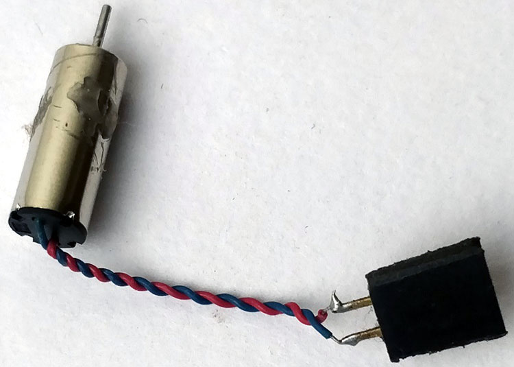
The coreless DC motor that is used in this project is shown in the picture below. You can find them easily since they are widely using in mini drones. Just look for 8520 Magnetic Micro Coreless Motor and you will find these.
Now, there are certain drawbacks to using DC motors for an RC car. The first thing is they provide very low starting torque hence our RC car should be as lightweight as possible. This is why I decided to build the entire car on top of a PCB using SMD components and reduces the board size as much as possible. The second problem is its high speed, 39000 RPM (RPM of the shaft) is hard to handle, so we need a speed control circuit on the Arduino side, which we built using a MOSFET. The third thing is that these motors will be powered by a single lithium-polymer battery with an operating voltage between 3.6V to 4.2V, so we have to design our circuit to operate on 3.3V. This is why we have used a 3.3V Arduino Pro mini as the brain of our RC car. With these problems sorted out, let’s look at the materials required to build this project.
Materials Required
- 3.3V Arduino Pro Mini
- Arduino Nano
- NRF24L01 – 2pcs
- Joystick Module
- SI2302 MOSFET
- 1N5819 Diode
- Coreless BLDC Motors
- AMS1117-3.3V
- Lithium Polymer battery
- Resistors, Capacitors,
- Connecting wires
RF Joystick for RC car using Arduino
As mentioned earlier the RC car will be controlled remotely using an RF Joystick. This Joystick will also be built using an Arduino along with an nRF24L01 RF module, we have also used the Joystick module to control our RC in the required direction. If you are completely new to these two modules, you can consider reading Interfacing Arduino with nRF24L01 and Interfacing Joystick with Arduino articles to learn how they work and how to use them. To build your Arduino RF Remote Joystick you can follow the below Circuit Diagram.

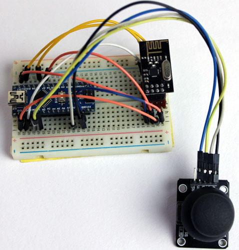
The RF Joystick circuit can be powered using the USB port of the nano board. The nRF24L01 module operates only on 3.3V, hence we have used the 3.3V pin on Arduino. I have constructed the circuit on a breadboard and it looks like below, you can also create a PCB for this if required.
The Arduino Code for RF Joystick circuit is pretty simple, we have to read the X value and Y value from our Joystick and send it to the RC car through the nRF24L01. The complete program for this circuit can be found at the bottom of this page. We will not get into the explanation of that since we have already discussed it in the interfacing project link shared above.
Arduino RC Car Circuit Diagram
The complete circuit diagram for our Remote controlled Arduino Car is shown below. The circuit diagram also includes an option to add two TCRT5000 IR modules to our car. This was planned to enable our RC car to work as a line following robot so that it can work on its own without being controlled externally. However, for the sake of this project we will not be concentrating on it, stay tuned for another project tutorial in which we will try building the “Fastest Line Follower Robot”. I have combined both the circuits on a single PCB for the ease of building, you can ignore the IR sensor and Op-amp section for this project.

The RC car will be powered by the Lipo Battery connected to terminal P1. The AMS117-3.3V is used to regulate 3.3V for our nRF24L01 and our pro-mini-board. We can also power the Arduino board directly on the raw pin but the on-board 3.3V voltage regulator on pro mini will not be able to supply enough current to our RF modules, hence we have used an external voltage regulator.
To drive our two BLDC motor, we have used two SI2302 MOSFETs. It is important to make sure that these MOSFETS can be driven by 3.3V. If you can’t find the exact same part number, you can look for equivalent MOSFETs with the below transfer characteristics

The motors can consume peak current as high as 7A (continuous was tested to be 3A with load), hence the MOSFET drain current should be 7A or more and it should turn on completely at 3.3V. As you can see here the MOSFET that we selected can provide 10A even at 2.25V so it’s an ideal choice.
Fabricating PCB for Arduino RC Car
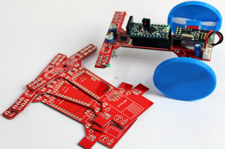
The fun part with the building this project was the PCB Development. The PCB’s here not only forms the circuit but also acts as a Chassis for our Car, so we planned a car looking shape for it with options to easily mount our motors. You can also try designing your own PCB using the circuit above or you can use my PCB design which looks like this below once completed.
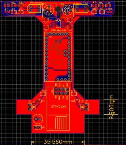
As you can see I have designed the PCB to easily mount the battery, motor, and other components. You can download the Gerber file for this PCB from the link. Once you are ready with the Gerber file, its time to get it fabricated. To get your PCBs easily done by PCBGOGO follow the steps below
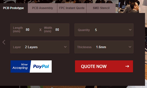
Step 1: Get into www.pcbgogo.com, sign up if this is your first time. Then, in the PCB Prototype tab enter the dimensions of your PCB, the number of layers and the number of PCB you require. My PCB is 80cm×80cm so the tab looks like this below.
Step 2: Proceed by clicking on the Quote Now button. You will be taken to a page where to set a few additional parameters if required like the material used track spacing etc. But mostly the default values will work fine. The only thing that we have to consider here is the price and time. As you can see the Build Time is only 2-3 days and it just costs only $5 for our PSB. You can then select a preferred shipping method based on your requirements.
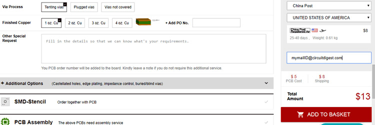
Step 3: The final step is to upload the Gerber file and proceed with the payment. To make sure the process is smooth PCBGOGO verifies if your Gerber file is valid before proceeding with the payment. This way you can sure that your PCB is fabrication friendly and will reach you as committed.
Assembling the PCB
After the board was ordered, it reached me after some days though courier in a neatly labeled well-packed box and like always the quality of the PCB was awesome. I am sharing a few pictures of the boards below for you to judge.
I turned on my soldering rod and started assembling the Board. Since the Footprints, pads, vias, and silkscreen are perfect of the right shape and size, I had no problem assembling the board. The board was ready in just 10 minutes from the time of unpacking the box.
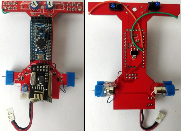
A few pictures of the board after soldering are shown below.
3D Printing Wheels and Motor Mount
As you might have noticed in the above picture, we need to 3D our motor mount and wheels for the robot. If you have used our PCB Gerber file shared above, then you might as well use a 3D model by downloading it from this thingiverse link.
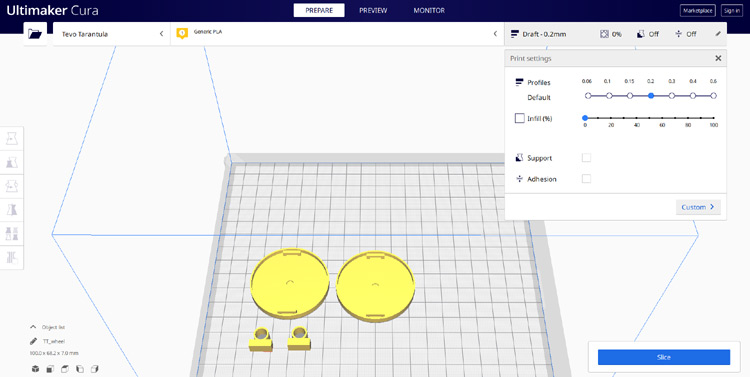
I have used Cura to slice my models and printed them using Tevo Terantuala with no supports and 0% infill for reducing weight. You can alter the setting as suited for our printer. Since the motors rotate very fast, I found it tough to design a wheel that will fit snug and tight to the motor shaft. Hence I decided to use the drone blades inside the wheel as you can see below

I found this to be more reliable and sturdy, however, do experiment with different wheel designs and let me know in the comment section what worked for you.
Programming the Arduino
The complete program (both Arduino nano and pro mini) for this project can be found at the bottom of this page. The explanation of your RC program is as follows
We start the program by including the required header file. Note that, the nRF24l01 module requires a library to be added to your Arduino IDE, you can download RF24 Library from Github using this link. Apart from that, we have already defined the minimum speed and maximum speed for our robot. The minimum and maximum range are 0 to 1024 respectively.
#define min_speed 200
#define max_speed 800
#include <SPI.h>
#include "RF24.h"
RF24 myRadio (7, 8);
Then inside the setup function, we initialize our nRF24L01 module. We have used the 115 bands since it is not congested and has set the module to operate with low power, you can also play around with these settings.
void setup() {
  Serial.begin (9600);
  myRadio.begin();
  myRadio.setChannel(115);  //115 band above WIFI signals
  myRadio.setPALevel(RF24_PA_MIN); //MIN power low rage
  myRadio.setDataRate( RF24_250KBPS ) ;  //Minimum speed
}
Next in the main loop function, we will only execute the ReadData function with which we will be constantly reading the value sent from our Transmitter joystick module. Note that the pipe address mentioned in the program should be the same as the one mentioned in the transmitter program. We have also printed the value that we receive for debugging purposes. Once the value is successfully read we will execute the Control Car function to control our RC car based on the value received from the
Rf module.
void ReadData()
{
  myRadio.openReadingPipe(1, 0xF0F0F0F0AA); //Which pipe to read, 40 bit Address
  myRadio.startListening(); //Stop Transminting and start Reveicing
  if ( myRadio.available())
  {
    while (myRadio.available())
    {
      myRadio.read( &data, sizeof(data) );
    }
    Serial.print("\nReceived:");
    Serial.println(data.msg);
    received = data.msg;
    Control_Car();
  }
}
Inside the Control Car function, we will control motors connected to the PWM pins using the analog write function. In our transmitter program we have converted the Analog values from A0 and A1 pin of Nano to 1 to 10, 11 to 20, 21 to 30 and 31 to 40 for controlling the car in forward, reverse, left and right respectively. The below program is used to control the robot in a forward direction
if (received>=1 && received <=10) // Move Forward
  {
    int PWM_Value =  map (received, 1, 10, min_speed, max_speed);
    analogWrite(R_MR,PWM_Value);
    analogWrite(L_MR,PWM_Value);
  }
Similarly, we can also write three more functions for reverse, left, and right control as shown below.
    if (received>=11 && received <=20) // Break
  {
    int PWM_Value =  map (received, 11, 20, min_speed, max_speed);
    analogWrite(R_MR,0);
    analogWrite(L_MR,0);
  }
    if (received>=21 && received <=30) // Turn left
  {
    int PWM_Value =  map (received, 21, 30, min_speed, max_speed);
    analogWrite(R_MR,PWM_Value);
    analogWrite(L_MR,0);
  }
      if (received>=31 && received <=40) // Turn Right
  {
    int PWM_Value =  map (received, 31, 40, min_speed, max_speed);
    analogWrite(R_MR,0);
    analogWrite(L_MR,PWM_Value);
  }
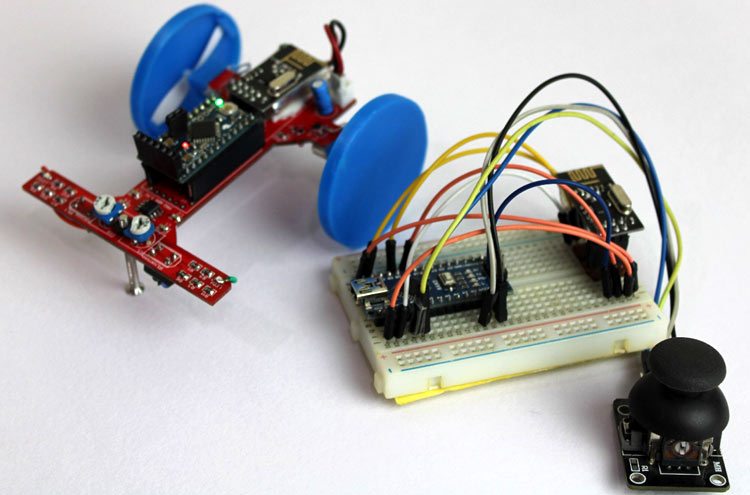
Working of Arduino RC Car
After you are done with the code, upload it to your pro-mini-board. Remove the battery and your board through the FTDI module for testing. Launch your code, open serial battery and you should receive the value from your transmitter Joystick module. Connect your battery and your motors should also start to rotate.
The complete working of the project can be found in the video linked at the bottom of this page. If you have any questions leave them in the comment section. You can also use our forums to get quick answers for your other technical questions.
Complete Project Code
RF Remote Joystick
/*Code to transmit RF values to Arduino

 *

 * Pin Conections

 *  CE - 7

    MISO - 12

    MOSI - 11

    SCK - 13

    CS - 8

    A0 - JoyX

    A1 - JoyY

*/

#include <SPI.h>

#include "RF24.h"

RF24 myRadio (7, 8);

struct package

{

  int msg = 0;

};

byte addresses[][6] = {"0"};

typedef struct package Package;

Package data;

void setup()

{

  Serial.begin(9600);

  myRadio.begin();

  myRadio.setChannel(115);  //115 band above WIFI signals

  myRadio.setPALevel(RF24_PA_MAX); //MAX power long rage

  myRadio.setDataRate( RF24_250KBPS ) ;  //Minimum speed

  delay(500);

  Serial.print("Remote Initialized");

}

  int forward;

  int reverse;

  int left;

  int right;

void loop()

{

 int xValue = analogRead(A0); //Read JoyX value

 int yValue = analogRead(A1); //Read JoyY Value

 //Serial.print(xValue); Serial.print(" , "); Serial.println(yValue);

 if (xValue>560 && xValue<1000) // Filter JoyX for up

 {

 forward = map (xValue, 560, 1000, 1, 10); //Convert Joyx-up to 0-10

 //Serial.print("F="); Serial.println(forward);

 data.msg = forward; WriteData(); delay(50);

 }

 if (xValue<500 && xValue > 10) // Filter JoyX for break

 {

 reverse = map (xValue, 10, 500, 20, 11); //Convert JoyX-down to 11-20

 //Serial.print("B="); Serial.println(reverse);

 data.msg = reverse; WriteData(); delay(50);

 }

 else if (yValue>600 && yValue<1000) // Filter JoyY for right

 {

 right = map (yValue, 600, 1000, 21, 30); //Convert JoyY-right to 21-30

 //Serial.print("R="); Serial.println(right);

 data.msg = right; WriteData(); delay(50);

 }

 else if (yValue<450 && yValue > 10) // Filter JoyY for left

 {

 left = map (yValue, 10, 450, 40, 31); //Convert JoyY-left to 31-40

 //Serial.print("L="); Serial.println(left);

 data.msg = left; WriteData(); delay(50);

 }

/* else

 {

  Serial.println("Rest");

  data.msg = 0; WriteData(); delay(50);

 }

*/

}

void WriteData()

{

  myRadio.stopListening();  //Stop Receiving and start transminitng

  myRadio.openWritingPipe( 0xF0F0F0F0AA); //Sends data on this 40-bit address

  myRadio.write(&data, sizeof(data));

  //Serial.print("\nSent:");

  //Serial.println(data.msg);

  delay(50);

}

void ReadData()

{

myRadio.openReadingPipe(1, 0xF0F0F0F066); // Which pipe to read, 40 bit Address

  myRadio.startListening(); //Stop Transminting and start Reveicing

  if ( myRadio.available())

  {

    while (myRadio.available())

    {

      myRadio.read( &data, sizeof(data) );

    }

    Serial.print("\nReceived:");

    Serial.println(data.msg);

  }

}

BLDC Motor
/*CE - 7

MISO - 12

MOSI - 11

SCK - 13

CS - 8

Recently tested with nano

*/

/*PIN DEFANITIONS*/

#define R_IR 3

#define L_IR 4

#define L_MR 5

#define R_MR 6

#define min_speed 200

#define max_speed 800

#include <SPI.h>

#include "RF24.h"

RF24 myRadio (7, 8);

struct package

{

  int msg;

};

typedef struct package Package;

Package data;

byte addresses[][6] = {"0"};

void setup() {

  pinMode(R_IR, INPUT);

  pinMode(L_IR, INPUT);

  pinMode(L_MR, OUTPUT);

  pinMode(R_MR, OUTPUT);

  Serial.begin (9600);

  myRadio.begin();

  myRadio.setChannel(115);  //115 band above WIFI signals

  myRadio.setPALevel(RF24_PA_MIN); //MIN power low rage

  myRadio.setDataRate( RF24_250KBPS ) ;  //Minimum speed

}

int received;

void loop() {

ReadData();

}

void Control_Car()

{

  if (received>=1 && received <=10) // Move Forward

  {

    int PWM_Value =  map (received, 1, 10, min_speed, max_speed);

    analogWrite(R_MR,PWM_Value);

    analogWrite(L_MR,PWM_Value);

  }

    if (received>=11 && received <=20) // Break

  {

    int PWM_Value =  map (received, 11, 20, min_speed, max_speed);

    analogWrite(R_MR,0);

    analogWrite(L_MR,0);

  }

    if (received>=21 && received <=30) // Turn Right

  {

    int PWM_Value =  map (received, 21, 30, min_speed, max_speed);

    analogWrite(R_MR,PWM_Value);

    analogWrite(L_MR,0);

  }

      if (received>=31 && received <=40) // Turn Right

  {

    int PWM_Value =  map (received, 31, 40, min_speed, max_speed);

    analogWrite(R_MR,0);

    analogWrite(L_MR,PWM_Value);

  }

}

void ReadData()

{

  myRadio.openReadingPipe(1, 0xF0F0F0F0AA); //Which pipe to read, 40 bit Address

  myRadio.startListening(); //Stop Transminting and start Reveicing

  if ( myRadio.available())

  {

    while (myRadio.available())

    {

      myRadio.read( &data, sizeof(data) );

    }

    Serial.print("\nReceived:");

    Serial.println(data.msg);

    received = data.msg;

    Control_Car();

  }

  else  //If not data from RF

  {

  //analogWrite(R_MR,0);

  //analogWrite(L_MR,0);

  }

}

void WriteData()

{

  myRadio.stopListening(); //Stop Receiving and start transminitng

  myRadio.openWritingPipe(0xF0F0F0F066);//Sends data on this 40-bit address

  myRadio.write(&data, sizeof(data));

  Serial.print("\nSent:");

  Serial.println(data.msg);

  delay(300);

}

Hi, great project! Please when you decide to build the fastest line following car send email to [email protected] as a teacher of physics am wondering if you can add ir optical speed sensor to both motor's and via Bluetooth to transmit to PC?(for line following car) Thanks