

The first thing that comes in mind when listening to the word Joystick is the game controller. Yes, it’s exactly the same and can be used for gaming purposes. Apart from gaming, it has many other applications in DIY electronics. This joystick is nothing but a combination of two potentiometers for the X and Y planes, respectively. It reads the voltage through the potentiometer and gives an analog values to the Arduino, and the analog values changes as we move the joystick shaft (which is simply the potentiometer pointer). To control four LEDs, each of which represents a direction of movement for the joystick, we have connected the joystick with Arduino Uno
Table of Contents
In this Circuit, we are interfacing Joystick with Arduino simply by controlling four LEDs as per the movement of the Joystick. We have placed 4 LEDs in such a way that they represents the direction of the joystick shaft movement. This joystick also has a push button, which can be used for various other purposes or can be left idle. A single LED is also attached to the joystick switch; when the joystick button is pressed, this LED will turn on. This interactive Arduino joystick control Tutorial shows how to translate analog joystick signals into real-time movement.
Required Components: Joystick Arduino Projects
- Arduino UNO
- Joystick Module
- LEDs-5
- Resistor: 100ohm-3
- Connecting wires
- Breadboard
Joystick Module Circuit Diagram
The Joystick circuit diagram clearly shows how to use an interfacing joystick with Arduino. It's a great opportunity to build interactive electronics and learn about analog signal processing.

Joystick Module Overview
Joysticks are available in different shapes and sizes. A typical Joystick module is shown in the figure below. This Joystick Module Arduino Projects typically provides Analog Outputs and the output voltages provided by this module keep changing according to the direction in which we move it. And we can get the direction of movement by interpreting these voltage changes using some microcontroller. Previously we interfaced Joystick with AVR and Raspberry Pi.
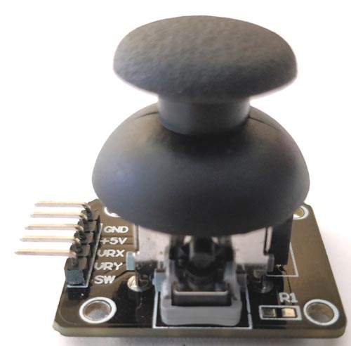
This joystick module has two axes as you can see. They are X-axis and Y-axis. Each axis of JOYSTICK is mounted to a potentiometer or pot. The midpoints of these pots are driven out as Rx and Ry. So Rx and Ry are variable points to these pots. When the Joystick is in standby, Rx and Ry act as a voltage divider.
When the joystick is moved along the horizontal axis, the voltage at Rx pin changes. Similarly, when it is moved along the vertical axis, the voltage at Ry pin changes. So we have four directions of Joystick on two ADC outputs. When the stick is moved, the voltage on each pin goes high or low depending on direction.
Here, we are connecting this Joystick module with the Arduino UNO which comes with an inbuilt ADC (Analog to Digital Converter) mechanism as shown in the video at the end. Learn more about using Arduino’s ADC here.
Code and Explanation
Complete Arduino Code is mentioned at the end.
In code below, we have defined X and Y axis of the Joystick module for analog pins A0 and A1, respectively.
#define joyX A0
#define joyY A1
Now, in the below code, we are initializing PIN 2 of Arduino for the Switch (push button) of the Joystick module, and the value of buttonstate and buttonstate1 will be 0 at the start.
int button=2;
int buttonState = 0;
int buttonState1 = 0;
In the below code, we are setting up the baud rate to 9600 and defining Pin 7 as an output pin and Button Pin as an input Pin. Initially, the button pin will remain high until the Switch is pressed.
void setup() {
  pinMode(7,OUTPUT);
  pinMode(button,INPUT);
  digitalWrite(button, HIGH);
  Serial.begin(9600);
}
Here, in this code we are reading the values from the analog pin A0 and A1 and printing serially.
int xValue = analogRead(joyX);
int yValue = analogRead(joyY);
  Serial.print(xValue);
  Serial.print("\t");
  Serial.println(yValue);
The conditions, for turning the LED on and off as per the movement of the Joystick shaft, are defined in the code below. Here we are just taking analog values of voltage at pins A0 and A1 of Arduino. These analog values will change as we move the joystick, and the LED will glow according to the movement of the joystick.

This condition is for movement of Joystick shaft in -Y axis direction
 if (xValue>=0 && yValue<=10){
    digitalWrite(10, HIGH);
  }
  else{digitalWrite(10, LOW);}
This condition is for movement of Joystick shaft in -X axis direction
  if (xValue<=10 && yValue>=500){
    digitalWrite(11, HIGH);
  }
  else{digitalWrite(11, LOW);}
This condition is for movement of Joystick shaft in +X axis direction
  if (xValue>=1020 && yValue>=500){
    digitalWrite(9, HIGH);
  }
  else{digitalWrite(9, LOW);}
This condition is for movement of Joystick shaft in +Y axis direction
  if (xValue>=500 && yValue>=1020){
    digitalWrite(8, HIGH);
  }
  else{digitalWrite(8, LOW);}
When we move the joystick shaft diagonally, then one position comes when the analog value of X and Y will be 1023 and 1023 respectively, both Pin 9 and Pin 8 LEDs will glow. Because it satisfies the condition of the LED. So, for removing that mismatch, we have given a condition that if the value of (X, Y) is (1023, 1023), then both the LEDs remain inthe OFF condition
  if (xValue>=1020 && yValue>=1020)  {
    digitalWrite(9, LOW);
    digitalWrite(8, LOW);
  }
The condition below is used to operate the LED connected to the Pushbutton Switch. As we press the Joystick switch, the LED will turn ON and latch until the button is released. It's optional to use the Push button switch on the Joystick module.
  if (buttonState == LOW)  {
    Serial.println("Switch = High");
    digitalWrite(7, HIGH);
  }
  else{digitalWrite(7, LOW);}
Controlling LEDs using a Joystick with Arduino

After uploading the code to the Arduino and connecting the components as per the circuit diagram, we can now control the LEDs with a Joystick. We can turn on the four LEDs in each direction according to the Joystick shaft movement. The Joystick has two potentiometers inside it, one is for X-axis movement and another is for Y-axis movement. Each potentiometer is getting 5V from the Arduino. As we move the joystick, the voltage value changes, and the analog values at Analog pins A0 and A1 also changes.
So, from the Arduino, we are reading the analog values for the X and Y axis and turning ON the LEDs as per the axis movement of the Joystick. A push button switch on the Joystick module is used to control the single LED in the circuit, as shown in the video below.
Frequently Asked Questions
⇥ How precise is the Arduino Uno's joystick module?
With a center value of about 512, the potentiometers on the joystick provide analog values via Arduino's 10-bit ADC (0–1023). Because of noise and mechanical flaws, accuracy is ±5–10 counts. As recommended by other guides, calibrate by averaging 100 readings for each axis (e.g., center, max, min) to increase precision.
⇥ What voltage does the joystick module operate on?
Most joystick modules work with both 3.3V and 5V systems. When connected to Arduino Uno's 5V pin, it outputs 0-5V analog signals that correspond to 0-1023 digital values.
⇥ How can I calibrate my joystick for better accuracy?
Read the center position values when the joystick is at rest, then map the ranges accordingly. Use the map() function to convert raw values (0-1023) to your desired range, accounting for dead zones around the center.
⇥ Can I create a USB joystick with Arduino for computer gaming?
Yes, you can create USB HID joysticks using Arduino Leonardo or Pro Micro boards. These boards have native USB capabilities that allow them to act as usb joystick Arduino devices. This advanced application extends beyond a basic joystick with Arduino Uno projects and requires HID library programming.
Project Summary and GitHub Repository
This comprehensive tutorial demonstrates how to interface a dual-axis analog joystick with Arduino Uno for LED control applications. The project covers fundamental concepts of the joystick connection to Arduino. You can download the complete project files, including Arduino code, circuit diagrams, wiring guides, and detailed documentation.


Simple Interfacing Joystick Project for Beginners
Explore our comprehensive collection of joystick interfacing tutorials with different microcontrollers and platforms. Each tutorial includes complete circuit diagrams, code examples, and step-by-step implementation guides for building advanced joystick module arduino projects.

Joystick Interfacing with AVR Microcontroller
In this tutorial we are going to interface a joystick module with atmega8 microcontroller. A joystick is an input module used for communication. It basically makes easy the user machine communication.

Interfacing a Joystick with Raspberry Pi
In this session, we are going to interface a Joystick with a Raspberry Pi. A joystick is primarily used to play various games. Although USB-type joysticks are easy to connect, but today we are going to connect the Joystick through Raspberry Pi GPIO pins,

Interfacing Dual Axis Joystick Module with Arduino
Even though the working principle behind these is very basic, they provide excellent control and degree of resolution in many fields. The application of the Joystick is limitless. We can find joysticks in various products from game controllers to advanced UAV navigation systems, in their various forms.
Complete Project Code
#define joyX A0
#define joyY A1
int button=2;
int buttonState = 0;
int buttonState1 = 0;
void setup() {
  pinMode(7,OUTPUT);
  pinMode(button,INPUT);
  digitalWrite(button, HIGH);
  Serial.begin(9600);
}

void loop() {
 int xValue = analogRead(joyX);
 int yValue = analogRead(joyY);

  Serial.print(xValue);
  Serial.print("\t");
  Serial.println(yValue);

  buttonState = digitalRead(button);
  Serial.println(buttonState);
  if (xValue>=0 && yValue<=10)
  {
    digitalWrite(10, HIGH);
  }
  else{digitalWrite(10, LOW);}
  if (xValue<=10 && yValue>=500)
  {
    digitalWrite(11, HIGH);
  }
  else{digitalWrite(11, LOW);}
  if (xValue>=1020 && yValue>=500)
  {
    digitalWrite(9, HIGH);
  }
  else{digitalWrite(9, LOW);}
  if (xValue>=500 && yValue>=1020)
  {
    digitalWrite(8, HIGH);
  }
  else{digitalWrite(8, LOW);}
  if (xValue>=1020 && yValue>=1020)
  {
    digitalWrite(9, LOW);
    digitalWrite(8, LOW);
  }
  if (buttonState == LOW)
  {
    Serial.println("Switch = High");
    digitalWrite(7, HIGH);
  }
  else{digitalWrite(7, LOW);}
  buttonState1 = digitalRead(7);
  Serial.println(buttonState1);
  delay(50);
}
Comments
Thanks for the heads up, yes the pin declaration in missing in the program
hi there, how do I update thie code as per your comment?
I've
How do I fix the values for the joystick in the code?
What do you wanna fix? Elaborate your problem if at all you are seeking any solution from other. Because only if some knows your problem they can help you
The lighting of each LED except pin 7 is very dim, is there anyway to modify the code so the light becomes very bright if the coordinates are met?
Just reduce the value of current limiting resistors attached to the LED and thwn the LED will be brighter
I had a similar problem. Changing the code to designate pins 7, 8, 9, 10, and 11 as output fixed it for me.
HI,
THE CODE IS NOT WORKING.
Hi,
Tried code on joystic with following output voltages:
Centre = 2.5V
Y+ 2.5V to 0V (Max Point)
Y- 2.5V to 5V (Max Point)
X+ 2.5V to 0V (Max Point)
X- 2.5V to 5V (Max Point)
Any idea why the code only works for X plus?

This code didn't work for my ,because you forgot to set the LED pins 8,9,10 and 11 as an Output
Beside that I found it a nice educational project.