

In this session we are going to Interface a Joystick with Raspberry Pi. Joystick is primarily used to play various games. Although USB type joysticks are easy to connect, but today we are going to connect Joystick through Raspberry Pi GPIO pins, this will come in handy in many cases.
Raspberry Pi and Joystick Module:
Joysticks are available in different shapes and sizes. A typical Joystick module is shown in the figure below. This Joystick module typically provides Analog Outputs and the output voltages provided by this module keep changing according to the direction in which we move it. And we can get the direction of movement by interpreting these voltage changes using some microcontroller. Previously we have used AVR Microcontroller with Joystick.
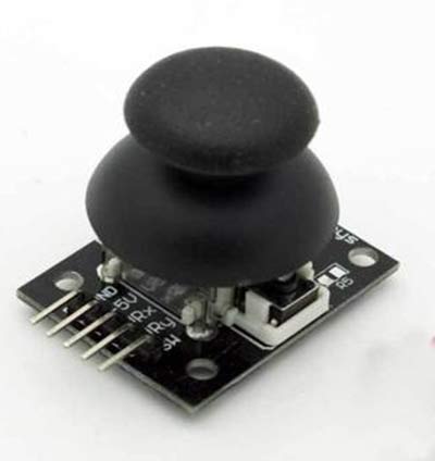
This joystick module has two axes as you can see. They are X-axis and Y-axis. Each axis of JOY STICK is mounted to a potentiometer or pot. The mid points of these pots are driven out as Rx and Ry. So Rx and Ry are variable points to these pots. When the Joystick is in standby, Rx and Ry act as voltage divider.
When joystick is moved along the horizontal axis, the voltage at Rx pin changes. Similarly, when it is moved along the vertical axis, the voltage at Ry pin changes. So we have four directions of Joystick on two ADC outputs. When the stick is moved, the voltage on each pin goes high or low depending on direction.
As we know Raspberry Pi does not have an internal ADC (Analog to Digital Converter) mechanism. So this module cannot be connected directly to the Pi. We will use Op-amp based comparators to check the voltage outputs. These OP-Amps provide signals to Raspberry Pi and Pi toggles the LEDs to depending upon the signals. Here we have used four LEDs to indicate the movement of Joystick in four directions. Check the demonstration Video at the end.
Each of the 17 GPIO pins cannot take voltage higher than +3.3V, so the Op-amp outputs cannot be higher than 3.3V. Hence we have chosen op-amp LM324, this IC has quad operational amplifier which can work at 3V. With this IC, we have suitable outputs for outputs for our Raspberry pi GPIO Pins. Learn more about GPIO Pins of Raspberry Pi here. Also check our Raspberry Pi Tutorial Series along with some good IoT Projects.
Components Required:
Here we are using Raspberry Pi 2 Model B with Raspbian Jessie OS. All the basic Hardware and Software requirements are previously discussed, you can look it up in the Raspberry Pi Introduction and Raspberry PI LED Blinking for getting started, other than that we need:
- 1000µF capacitor
- Joystick Module
- LM324 Op-amp IC
- 1KΩ resistor (12 pieces)
- LED (4 pieces)
- 2.2KΩ resistor (4 pieces)
Circuit Diagram:
There are four OP-AMP comparators inside LM324 IC for detecting four directions of Joystick. Below is the diagram of LM324 IC from its datasheet.

The connections which are done for Interfacing Joystick module with Raspberry Pi are shown in the circuit diagram below. U1:A, U1:B, U1:C, U1:D indicates the four comparators inside LM324. We have shown each comparator in the circuit diagram with the corresponding Pin no. of LM324 IC.

Working Explanation:
For detecting the movement of Joystick along the Y-axis, we have OP-AMP1 or U1:A and OP-AMP2 or U1:B, and for detecting the movement of Joystick along the X-axis, we have OP-AMP3 or U1:C and OP-AMP4 or U1:D.
OP-AMP1 detects the downside movement of joystick along Y-axis:
Negative terminal of comparator U1:A is provided with 2.3V (using voltage divider circuit by 1K and 2.2K) and Positive terminal is connected to Ry. On moving the joystick down along its Y-axis, Ry voltage increases. Once this voltage goes higher than 2.3V, OP-AMP provides +3.3V output at its output Pin. This HIGH logic output of OP-AMP will be detected by Raspberry Pi and Pi responds by toggling an LED.
OP-AMP2 detects the upside movement of joystick along Y-axis:
Negative terminal of comparator U1:B is provided with 1.0V (using voltage divider circuit by 2.2K and 1K) and Positive terminal is connected to Ry. On moving the joystick up along its Y-axis, Ry voltage decreases. Once this voltage goes lower than 1.0V, the OP-AMP output goes Low. This LOW logic output of OP-AMP will be detected by Raspberry Pi and Pi responds by toggling an LED.
OP-AMP3 detects the left side movement of joystick along X-axis:
Negative terminal of comparator U1:C is provided with 2.3V (using voltage divider circuit by 1K and 2.2K) and Positive terminal is connected to Rx. On moving the joystick left along its x-axis, Rx voltage increases. Once this voltage goes higher than 2.3V, OP-AMP provides +3.3V output at its output Pin. This HIGH logic output of OP-AMP will be detected by Raspberry Pi and Pi responds by toggling an LED.
OP-AMP4 detects the right side movement of joystick along X-axis:
Negative terminal of comparator U1:4 is provided with 1.0V (using voltage divider circuit by 2.2K and 1K) and Positive terminal is connected to Rx. On moving the joystick right along its x-axis, Rx voltage decreases. Once this voltage goes lower than 1.0V, the OP-AMP output goes Low. This LOW logic output of OP-AMP will be detected by Raspberry Pi and Pi responds by toggling an LED.
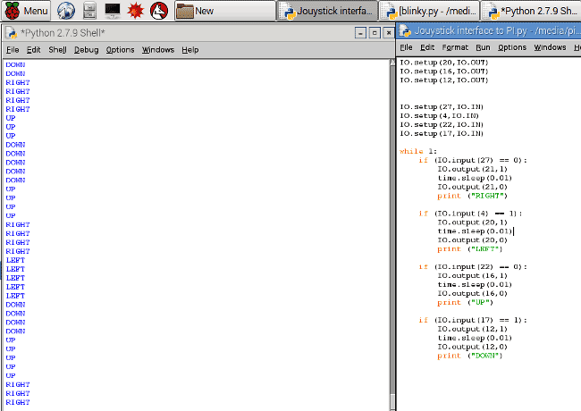
This way all the four logics, which determine the four directions of Joystick, get connected to Raspberry Pi. Raspberry Pi takes the outputs of these comparators as inputs and responds accordingly by toggling the LEDs. Below are the results shown on the Raspberry Pi’s terminal, as we have also printed the direction of Joystick on terminal using our Python Code.
Python code and video is given below. Code is easy and can be understood by the comments given in the code.
Complete Project Code
#working
import RPi.GPIO as IO    # calling for header file which helps in using GPIOs of PI
import time              # we are calling for time to provide delays in program
IO.setwarnings(False)    # do not show any warnings
IO.setmode (IO.BCM)      #programming the GPIO by BCM pin numbers (like PIN29 as GPIO5)
IO.setup(21,IO.OUT)      # initialize GPIO21 as an output
IO.setup(20,IO.OUT)
IO.setup(16,IO.OUT)
IO.setup(12,IO.OUT)
IO.setup(27,IO.IN)      # initialize GPIO27 as an input
IO.setup(4,IO.IN)
IO.setup(22,IO.IN)
IO.setup(17,IO.IN)
while 1:
    if (IO.input(27) == 0):  #If GPIO 27 goes low toggle LED on 21pin and print RIGHT
        IO.output(21,1)
        time.sleep(0.01)
        IO.output(21,0)
        print ("RIGHT")
    if (IO.input(4) == 1):   #If GPIO 4 goes high toggle LED on 20pin and print LEFT
        IO.output(20,1)
        time.sleep(0.01)
        IO.output(20,0)
        print ("LEFT")
    if (IO.input(22) == 0):  #If GPIO 22 goes low toggle LED on 16pin and print UP
        IO.output(16,1)
        time.sleep(0.01)
        IO.output(16,0)
        print ("UP")
    if (IO.input(17) == 1):  #If GPIO 17 goes high toggle LED on 12pin and print DOWN
        IO.output(12,1)
        time.sleep(0.01)
        IO.output(12,0)
        print ("DOWN")
