

In this tutorial we are going to interface a joystick module with atmega8 microcontroller. A JOY STICK is an input module used for communication. It basically makes easy the user machine communication. A joystick is shown in below figure.
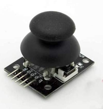
The joystick module has two axis - one is horizontal and other is vertical. Each axis of joystick is mounted to a potentiometer or pot or variable resistance. The mid points are brought down as Rx and Ry. These pins carry as output signal pins for JOYSTICK. When the stick is moved along horizontal axis , with the supply voltage present , the voltage at Rx pin changes.
The voltage at Rx increases when moved forward, the voltage at Rx pin decreases when moved backward. Similarly, the voltage at Ry increases when moved upward, the voltage at Ry pin decreases when moved downward.
So we have four directions of JOYSTICK on two ADC channels. At normal cases we have 1Volt on each pin under normal circumstances. When the stick is moved the voltage on each pin goes high or low depending on direction. So four directions as ( 0V,5V on channel 0) for x- axis; ( 0V,5V on channel 1) for y- axis.
We are going to use two ADC channels of ATMEGA8 to do the job. We are going to use channel 0 and channel 1.
Components Required
Hardware: ATMEGA8, power supply (5v), AVR-ISP PROGRAMMER, LED (4 pieces), 1000uF capacitor, 100nF capacitor (5 pieces), 1KΩ resistor (6 pieces).
Software: Atmel studio 6.1, progisp or flash magic.
Circuit Diagram and Working Explanation

The voltage across JOYSTICK is not completely linear; it will be a noisy one. To filter out the noise a capacitors are placed across each resistor in the circuit as shown in figure.
As shown in figure there are four LEDs in the circuit. Each LED represents each direction of JOYSTICK. When the stick is moved in a direction, then the corresponding LED glows.
Before going any further we need to talk about ADC of ATMEGA8,
In ATMEGA8, we can give Analog input to any of FOUR channels of PORTC, it doesn’t matter which channel we choose as all are same, we are going to choose channel 0 or PIN0 of PORTC.
In ATMEGA8, the ADC is of 10 bit resolution, so the controller can detect a sense a minimum change of Vref/2^10, so if the reference voltage is 5V we get a digital output increment for every 5/2^10 = 5mV. So for every 5mV increment in the input we will have a increment of one at digital output.
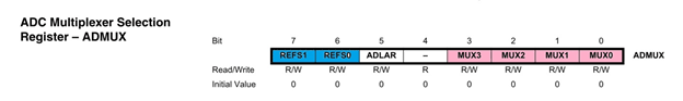
Now we need to set the register of ADC based on the following terms,
1. First of all we need to enable the ADC feature in ADC.
2. Here are going to get a maximum input voltage for ADC conversion is +5V. So we can set up maximum value or reference of ADC to 5V.
3. The controller has a trigger conversion feature that means ADC conversion takes place only after an external trigger, since we don’t want that we need to set the registers for the ADC to run in continuous free running mode.
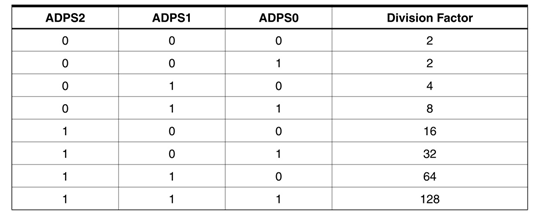
4. For any ADC, frequency of conversion (Analog value to Digital value) and accuracy of digital output are inversely proportional. So for better accuracy of digital output we have to choose lesser frequency. For normal ADC clock we are setting the presale of ADC to maximum value (2). Since we are using the internal clock of 1MHZ, the clock of ADC will be (1000000/2).
These are the only four things we need to know to getting started with ADC.
All the above four features are set by two registers:
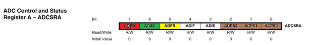
RED (ADEN): This bit has to be set for enabling the ADC feature of ATMEGA.
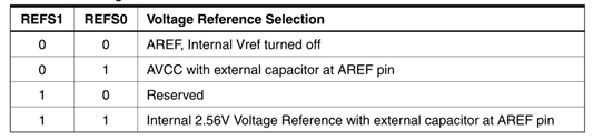
BLUE(REFS1,REFS0): These two bits are used to set the reference voltage (or max input voltage we are going to give). Since we want to have reference voltage 5V, REFS0 should be set, by the table.
YELLOW (ADFR): This bit must be set for the ADC to run continuously (free running mode).
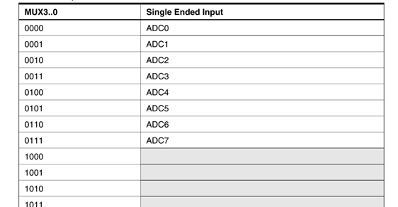
PINK (MUX0-MUX3): These four bits are for telling the input channel. Since we are going to use ADC0 or PIN0, we need not set any bits as by the table.
BROWN (ADPS0-ADPS2): these three bits are for setting the prescalar for ADC. Since we are using a prescalar of 2, we have to set one bit.
DARK GREEN (ADSC): this bit set for the ADC to start conversion. This bit can be disabled in the program when we need to stop the conversion.
Complete Project Code
               #include <avr/io.h>
//header to enable data flow control over pins
                #define F_CPU 1000000
//telling controller crystal frequency attached
                #include <util/delay.h>
//header to enable delay function in program

                #define    E   5
//giving name “enable”  to 5th pin of PORTD, since it Is connected to LCD enable pin
                #define RS  6
//giving name “registerselection” to 6th pin of PORTD, since is connected to LCD RS pin

                void send_a_command(unsigned char command);
                void send_a_character(unsigned char character);
               void send_a_string(char *string_of_characters);
                int main(void)
                {
                                DDRB = 0xFF;
                                      //putting portB and portD as output pins
                                DDRD = 0xFF;
                                _delay_ms(50);//giving delay of 50ms
                             DDRC = 0;//Taking portC as input.

              int HORIZONTAL=141;//neutral value on x-axis
                int VERTICAl = 151;// neutral value on y-axis
                int HORIZONTALMOV =0;
                int VERTICAlMOV =0;

                              ADMUX |=(1<<REFS0);//setting the reference of ADC

                              ADCSRA |=(1<<ADEN) |(1<ADPS2)|(1<ADPS1) |(1<<ADPS0);
//enabling the ADC,, setting prescalar 128

                                while(1)
                {
switch (ADMUX)//changing between channels by switch statement
                                                                {
                                                                                case 0x40://When ADMUX==0x40
                                                                                {
                                                                                                ADCSRA |=(1<<ADSC);//start ADC conversion
                                                                                while ( !(ADCSRA & (1<<ADIF)));//wait till ADC conversion
                                                                                                HORIZONTALMOV = ADC;//moving value
                                                                                                ADC=0;//reset ADC register
                                                                                                ADMUX=0x41;//changing channel
                                                                                                break;
                                                                                }
                                                                                case 0x41:
                                                                                {
                                                                                                ADCSRA |=(1<<ADSC);// start ADC conversion
                                                                                while ( !(ADCSRA & (1<<ADIF)));// wait till ADC conversion
                                                                                                VERTICAlMOV = ADC;// moving value
                                                                                                ADC=0;// reset ADC register
                                                                                                ADMUX=0x40;// changing channel
                                                                                                break;
                                                                                }
                                                                }

                                if (HORIZONTALMOV<HORIZONTAL-50)
                                {
                                                PORTD |=(1<<PIND3);
                                                _delay_ms(5);
                                                PORTD=0;
                                }


                                if (HORIZONTALMOV>(HORIZONTAL+50))
                                {
                                                PORTD |=(1<<PIND2);
                                                _delay_ms(5);
                                    PORTD=0;
                                }


                                if (VERTICAlMOV<VERTICAl-50)
                                {
                                                PORTD |=(1<<PIND1);
                                                _delay_ms(5);
                                                PORTD=0;
                                }
                                if (VERTICAlMOV>VERTICAl+50)
                                {
                                                PORTD |=(1<<PIND0);
                                                _delay_ms(5);
                                                PORTD=0;
                                }
                } }

#include <avr/io.h>
#include <util/delay.h>