

When thinking about the best way to control games, drones, robots, etc, the first control mechanism that comes to our mind will be a joystick. Even though the working principle behind these are very basic, they provide excellent control and degree of resolution in many fields. The application of the Joystick is limitless. We can find joysticks in various products from game controllers to advanced UAV navigation systems, in their various forms.
Dual Axis Joystick Module
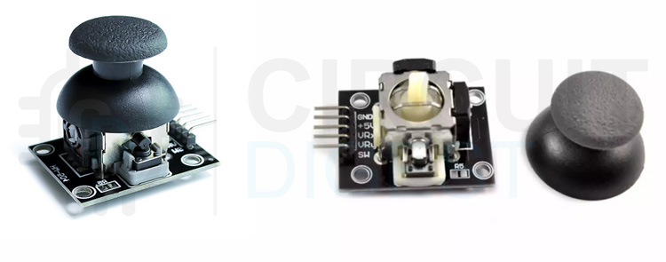
The Joystick module is similar to analog joysticks found in gamepads. It is made by mounting two potentiometers at a 90 degrees angle. The potentiometers are connected to a short stick centered by springs. The gif below shows how the joystick pivot mechanism is working.
The potentiometers act as voltage dividers. This module produces an output of around 2.5V from X and Y when it is in the resting position. Moving the joystick will cause the output to vary from 0v to 5V depending on its direction. If you connect this module to a microcontroller, you can expect to read a value of around 512 in its resting position (expect small variations due to tiny imprecisions of the springs and mechanism). When you move the joystick you should see the values change from 0 to 1023 depending on its position. The given example values are for a 5V microcontroller or a development board with 10bit ADC resolution like Arduino UNO or nano
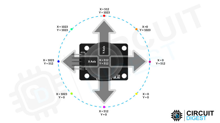
The above image shows the X and Y directions and also gives an indication of how the outputs will respond when the joystick is connected to an Arduino Uno and manipulated in various directions.
Specifications:
- Directional movements are simply two potentiometers - one for each axis.
- Dimensions: 34 x 34 x 15 (LxWxH) mm.
- Operating Voltage: 5V.
- 2.54mm pin interface leads.
Joystick Module Pinout
The Joystick module has a total of 5 pins. Two are for power, two are for X and Y potentiometers, and one is for the middle switch. The pinout of the module is as follows:

VCC - Provides power for the module, Connect to the 5V pin of the Arduino.
GND - Ground Connected to Ground pin of the Arduino.
VRx/VRy – VRx/VRy outputs from the potentiometer.
SW – Switch output. The output will be pulled low when pressed.
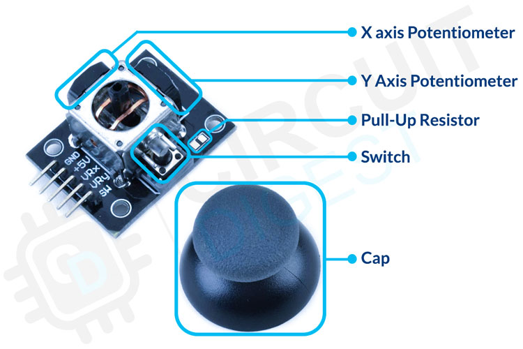
Joystick Module Parts
The Joystick itself only contains the two potentiometers for each axis and a switch to register the click. One side of the potentiometers is connected to the ground and the other to the VCC. The center pins are connected to the VRx and VRy pins respectively. Similarly, the switch is connected between the GND and the SW pins. And in some modules, there is also an unpopulated space for a pull-up resistor on board for the switch.
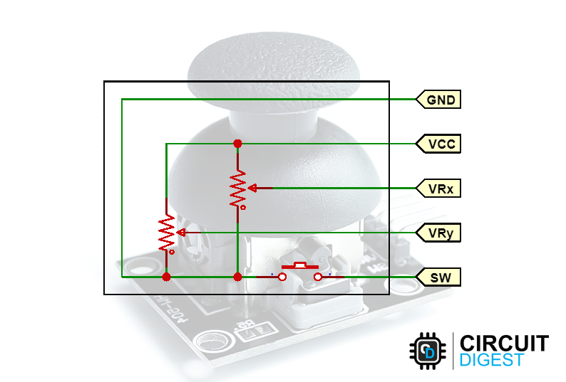
Joystick Module Circuit Diagram
The schematic diagram from the dual-axis joystick module is given below. As we have mentioned earlier, the joystick is actually pretty simple. It contains two potentiometers for the X and Y axis and a switch for registering clicks.
Commonly Asked Questions
What is a joystick module?
The Joystick module is similar to analog joysticks found in gamepads. It is made by mounting two potentiometers at a 90 degrees angle. The potentiometers are connected to a short stick centered by springs. This module produces an output voltage with respect to the position of each potentiometer. This output is then measured, and the position is calculated.
What are the advantages of a joystick?
- It is a very fast interface.
- It is easier to navigate.
- The control is in 3D (three dimensions).
- They provide fast interactions as required in most games and hence are used in games such as racing or flying styles etc.
How to interface a Joystick with Arduino?
You can simply read the voltage output from the VRx and VRy pins using the analog pins and then calculate the position from these two values.
Joystick not working properly or not working at all? Here is what you should check.
If your Joystick module is not working properly the first and important step is to make sure all the connections are correct. Once the connections are verified, we can move forward to the next diagnosing step. If the reading from the VRx and VRy is not proper or it jumps around too much, then there must be a problem with the potentiometers. You can gently pop the potentiometers out of their default position by lifting them slightly. Give them a good clean using IPA or a similar cleaning solution and then pop them back in, to see if this has fixed the issue. If not either replace the potentiometer or the module itself.
Arduino Joystick Module Interfacing Circuit Diagram
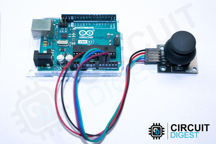
The following image shows the circuit diagram for interfacing the Joystick module with Arduino. Connect the VCC and GND pins of the module to the 5V and GND pins of the Arduino respectively. Connect the VRx, VRy, and SW pins to Arduino’s A0, A1, and A2 pins respectively.

Here is how the real-life connection looks.
Arduino Code for Interfacing Joystick Module
In this example, we are going to read the measurement from two analog inputs and one digital input. Then we will display the result on the serial monitor.
Code Explanation
The sketch starts by defining the connections to the Joystick module. The SW pin is connected to Arduino’s Pin A2 while the VRx and VRy pins are connected to Analog pins A0 and A1.
#define Xaxis_pin A0 // Arduino pin connected to the VRx Pin
#define Yaxis_pin A1 // Arduino pin connected to the VRy Pin
#define SW_pin A2 // Arduino pin connected to the SW Pin
In the setup() function, we initialized the SW pin as an input and keep it HIGH. This is as same as declaring the pin as INPUT_PULLUP. When the switch is pressed, this pin will be pulled to the ground. Thus, we can detect the button press by monitoring the state of this pin. We have also initialized the serial communication so that we can print all the necessary information into the serial monitor.
void setup() {
  pinMode(SW_pin, INPUT);
  digitalWrite(SW_pin, HIGH);
  Serial.begin(9600);
}
In loop() function, we continously read the value of SW pin using digitalRead() function, VRx & VRy pin using analogRead() and display on serial monitor.
void loop() {
  Serial.print("X-axis: ");
  Serial.print(analogRead(Xaxis_pin));
  Serial.print(" : ");
  Serial.print("Y-axis: ");
  Serial.print(analogRead(Yaxis_pin));
  Serial.print(" : ");
  Serial.print("Switch:  ");
  Serial.println(digitalRead(SW_pin));
  delay(200);
}
Joystick module Interfacing with Arduino
The below GIF shows how we have interfaced the Joystick module with the Arduino. As you can see as soon as I move the joystick, the corresponding values are displayed on the serial monitor.
Supporting Files


Complete Project Code
// Arduino Dual Axis Joystick Example
#define Xaxis_pin A0 // Arduino pin connected to the VRx Pin
#define Yaxis_pin A1 // Arduino pin connected to the VRy Pin
#define SW_pin A2 // Arduino pin connected to the SW Pin
void setup() {
  pinMode(SW_pin, INPUT);
  digitalWrite(SW_pin, HIGH);
  Serial.begin(9600);
}
void loop() {
  Serial.print("X-axis: ");
  Serial.print(analogRead(Xaxis_pin));
  Serial.print(" : ");
  Serial.print("Y-axis: ");
  Serial.print(analogRead(Yaxis_pin));
  Serial.print(" : ");
  Serial.print("Switch:  ");
  Serial.println(digitalRead(SW_pin));
  delay(200);
}

Hi
shouldn't work, I suggest