

Suppose you are sitting in a room and feeling cold and you want your heater to be automatically turned on, and then off after some time when room temperature is increased, then this project help you to control your home appliances automatically according to the temperature. Here we are controlling Home AC Appliances with Arduino based on the temperature. Here we have used Thermistor to read the temperature. We already interfaced Thermistor with Arduino and displayed the Temperature on LCD.
In this tutorial, we will attach a AC appliance with Relay and make a temperature controlled home automation system using Arduino. It also shows the temperature and appliance status on the 16*2 LCD display connected with the circuit.
Material Required
- Arduino UNO
- Relay (5v)
- 16*2 LCD display
- Light Bulb (CFL)
- NTC thermistor 10k
- Connecting wires
- Resistors (1k and 10k ohms)
- Potentiometer (10k)
Circuit Diagram

This Temperature based Home Automation System consists of various components like Arduino board, LCD display, Relay, and thermistor. The working mainly depends on the relay and thermistor as the temperature increased the relay will be turned on and if the temperature decreased below the preset value then Relay will be turned off. The Home appliance connected with the Relay will also turns on and off accordingly. Here we have used a CFL bulb as AC appliance. The whole triggering process and temperature value setting is performed by the programmed Arduino board. It also gives us details about the change in temperature in every half second and appliance status on the LCD screen.
Relay:
Relay is an electromagnetic switch, which is controlled by small current, and used to switch ON and OFF relatively much larger current. Means by applying small current we can switch ON the relay which allows much larger current to flow. A relay is a good example of controlling the AC (alternate current) devices, using a much smaller DC current. Commonly used Relay is Single Pole Double Throw (SPDT) Relay, it has five terminals as below:
When there is no voltage applied to the coil, COM (common) is connected to NC (normally closed contact). When there is some voltage applied to the coil, the electromagnetic field produced, which attracts the Armature (lever connected to spring), and COM and NO (normally open contact) gets connected, which allow a larger current to flow. Relays are available in many ratings, here we used 5V operating voltage relay, which allows 7A-250VAC current to flow.
The relay is configured by using a small Driver circuit which consists a Transistor, Diode and a resistor. Transistor is used to amplify the current so that full current (from the DC source – 9v battery) can flow through a coil to fully energies it. The resistor is used to provide biasing to the transistor. And Diode is used to prevent reverse current flow, when the transistor is switched OFF. Every Inductor coil produces equal and opposite EMF when switched OFF suddenly, this may cause permanent damage to components, so Diode must be used to prevent reverse current. A Relay module is easily available in the market with all its Driver circuit on the board or you can create it by using above components. Here we have used 5V Relay module


Calculating Temperature using Thermistor:
We know from the Voltage divider circuit that:
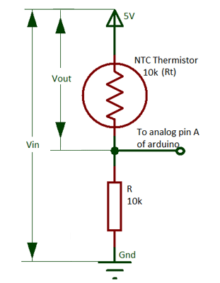
Vout= (Vin * Rt) / (R + Rt)
So the value of Rt will be:
Rt = R (Vin/Vout) – 1
Here Rt will be the resistance of the thermistor (Rt) and R will be 10k ohm resistor.
This equation is used for the calculation of thermistor resistance from the measured value of output voltage Vo. We can get the value of Voltage Vout from the ADC value at pin A0 of Arduino as shown in the Arduino Code given below.
Calculation of Temperature from the thermistor resistance
Mathematically the thermistor resistance can only be compute with the help of the Stein-Hart equation.
T = 1 / (A + B*ln(Rt) + C*ln (Rt)3 )
Where, A, B and C are the constants, Rt is the thermistor resistance and ln represents log.
The constant value for the thermistor used in the project is A = 1.009249522×10⁻³, B = 2.378405444×10⁻⁴, C = 2.019202697×10⁻⁷. These constant values can be obtained from the calculator here by entering the three resistance values of the thermistor at three different temperatures. You can either get these constant values directly from the datasheet of the Thermistor or you can get three resistance values at different temperature and get the Constants values using the given calculator.
So, for calculating the temperature we need the value of thermistor resistance only. After getting the value of Rt from the calculation given above put the values in the Stein-hart equation and we will get the value of temperature in the unit Kelvin. As there is a minor change in the output voltage cause change in the temperature.
Arduino code
Complete Arduino Code for this Temperature Controlled Home Appliances is given at the end of this article. Here we have explained few parts of it.
For performing mathematical operation we use Header file “#include <math.h>” and for LCD header file is “#include <LiquidCrystal.h>" and “#define RELAY 8” is used to assign the input pin for a relay. We have to assign the pins of the LCD by using the code.
#include <math.h>
#include "LiquidCrystal.h"
#define RELAY 8
LiquidCrystal lcd(6,7,5,4,3,2); // these are in format like LCD(Rs, EN, D4, D5, D6, D7)
For setup the Relay (as an output) and LCD at the time of start we have to write code in the void setup part
Void setup(){
 lcd.begin(16,2);
 lcd.clear();
pinMode(RELAY, OUTPUT);
}
For the calculation of temperature by Stein-Hart equation using the electrical resistance of thermistor we perform some simple mathematical equation in code as explained in calculation above:
float a = 1.009249522e-03, b = 2.378405444e-04, c = 2.019202697e-07;
float T, logRt, Tf, Tc;
float Thermistor(int Vo) {
logRt = log(10000.0*((1024.0/Vo-1)));
 T = (1.0 / (a + b*logRt + c* logRt * logRt * logRt)); // We get the temperature value in Kelvin from this Stein-Hart equation
 Tc = T - 273.15;                     // Convert Kelvin to Celsius
 Tf = (Tc * 1.8) + 32.0;              // Convert Kelvin to Fahrenheit
 return T;
}
In the below code the function thermistor is reading the value from the analog pin of the Arduino, and print the temperature value by performing the mathematical operation
lcd.print((Thermistor(analogRead(0))));
And that value is taken by the Thermistor function and then the calculation is start printing
float Thermistor(int Vo)
We have to write the code for the condition of turning light ON and OFF according to the temperature as we set the temperature value like if the temperature increase more than 28 degree Celsius the lights will turn ON of if less the lights remain off. So whenever the temperature goes above than 28 degrees, we need to make the RELAY Pin (PIN 8) high to make the Relay module ON. And when the temperature goes below 28 degrees, we need to make the RELAY pin low to turn off the Relay Module.
if (Tc > 28) digitalWrite(RELAY, HIGH),lcd.setCursor(0,1),lcd.print("Light status:ON "),delay(500);
else if (Tc < 28) digitalWrite(RELAY, LOW),lcd.setCursor(0,1),lcd.print("Light status:OFF"),delay(500);
Working of Temperature Controlled Home Automation System:
To give the supply to the Arduino you can power it via USB to your laptop or connect 12v adapter. A LCD is interfaced with Arduino to display temperature values, Thermistor and Relay is connected as per circuit diagram. The analog pin (A0) is used to check the voltage of thermistor pin at every moment and after the calculation using Stein-Hart equation through the Arduino code we are able to get the temperature and display it on LCD in the Celsius and Fahrenheit.
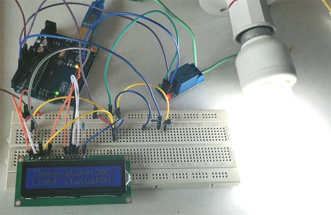
As the temperature increases more than 28 degree Celsius Arduino makes the Relay Module Turned On by making the Pin 8 HIGH (where the Relay module is connected) when the temperature goes below 28 Degree Arduino turns off the Relay Module by making the Pin LOW. CFL bulb will also turn On and Off according to Relay module.
This system can be very useful in Temperature controlled Fan and Automatic AC temperature controller project.
Also check our many types of Home Automations Projects using different technologies and Microcontrollers like:
- DTMF Based Home Automation
- GSM Based Home Automation using Arduino
- PC Controlled Home Automation using Arduino
- Bluetooth Controlled Home Automation using 8051
- IR Remote Controlled Home Automation using Arduino
- home automation project using MATLAB and Arduino
- RF Remote Controlled LEDs Using Raspberry Pi
- Smart Phone Controlled Home Automation using Arduino
- Voice Controlled Home Automation using ESP8266 and Android App
- RF based Home Appliances System without Microcontroller
- Raspberry Pi based Smart Phone Controlled Home Automation
Complete Project Code
#include <math.h>
#include "LiquidCrystal.h"
#define RELAY 8
LiquidCrystal lcd(6,7,5,4,3,2);
float A = 1.009249522e-03, B = 2.378405444e-04, C = 2.019202697e-07;
float T,logRt,Tf,Tc;
float Thermistor(int Vo) {
 logRt = log(10000.0*((1024.0/Vo-1)));
 T = (1.0 / (A + B*logRt + C*logRt*logRt*logRt));  // We get the temperature value in Kelvin from this Stein-Hart equation
 Tc = T - 273.15;                 // Convert Kelvin to Celcius
 Tf = (T * 1.8) + 32.0;           // Convert Kelvin to Fahrenheit
 return T;
}
void setup() {
 lcd.begin(16,2);
 lcd.clear();
pinMode(RELAY, OUTPUT);
}
void loop() {

  lcd.setCursor(0,0);
  lcd.print("Temperature:");
  lcd.print(int(Thermistor(analogRead(0))));
  lcd.print("C ");
  delay(500);  // wait 0.5 seconds before sampling temperature again
if (Tc > 28) digitalWrite(RELAY, HIGH),lcd.setCursor(0,1),lcd.print("Light status:ON "),delay(500);
else if (Tc < 28) digitalWrite(RELAY, LOW),lcd.setCursor(0,1),lcd.print("Light status:OFF"),delay(500);

}
Comments
Really nice work.
Can anyone point me in the right direction on how to get a good jump start in arduino circuit design.
Thanks alot
which circuit simulator did you use?

Thanks subscribe more