 in STM32F103C8: Controlling Speed of DC Fan")
In previous article we have seen about ADC conversion using STM32. In this tutorial, we will learn about PWM (Pulse Width Modulation) in STM32 and how can we control brightness of LED or speed of DC fan using PWM technique.
We know that there are two types of signal: Analog and Digital. Analog signals have voltages like (3V, 1V...etc) and digital signals have (1’ and 0’s). Sensors outputs are of analog signals and these analog signals are converted into digital using ADC, because microcontrollers only understand digital. After processing those ADC values, again the output needs to be converted into analog form to drive the analog devices. For that we use certain methods like PWM, Digital to Analog (DAC) converters etc.
What is PWM (Pulse with Modulation)?
PWM is a way to control the analog devices using digital value like controlling motor’s speed, brightness of a led etc. We know that motor and led works on analog signal. But the PWM doesn’t provide pure analog output, PWM looks like analog signal made by short pulses, which is provided by duty cycle.
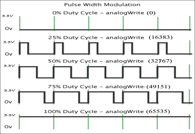
Duty cycle of the PWM
The percentage of time in which the PWM signal remains HIGH (on time) is called as duty cycle. If the signal is always ON it is in 100% duty cycle and if it is always off it is 0% duty cycle.
Duty Cycle =Turn ON time/ (Turn ON time + Turn OFF time)
PWM in STM32
STM32F103C8 has 15 PWM pins and 10 ADC pins. There are 7 timers and each PWM output is provided by a channel connected to 4 timers. It has 16-bit PWM resolution (216), that is counters and variables can be as large as 65535. With a 72MHz clock rate, a PWM output can have maximum period of about one millisecond.
- So value of 65535 gives FULL BRIGHTNESS of LED AND FULL SPEED of DC Fan (100% Duty Cycle)
- Likewise value of 32767 gives HALF BRIGHTNESS of LED AND HALF SPEED of DC Fan (50% Duty Cycle)
- And value of 13107 gives (20%) BRIGHTNESS AND (20%) SPEED (20% Duty Cycle)
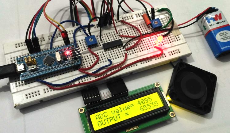
In this tutorial, we are using potentiometer and STM32 to vary the brightness of LED and speed of a DC fan by PWM technique. A 16x2 LCD is used to display ADC value (0-4095) and the modified variable (PWM value) that is output (0-65535).
Here are few PWM examples with other Microcontroller:
- Generating PWM using PIC Microcontroller with MPLAB and XC8
- Servo Motor Control with Raspberry Pi
- Arduino Based LED Dimmer using PWM
- Pulse width Modulation (PWM) using MSP430G2
Check all the PWM related projects here.
Components Required
- STM32F103C8
- DC fan
- ULN2003 Motor Driver IC
- LED (RED)
- LCD (16x2)
- Potentiometer
- Breadboard
- Battery 9V
- Jumper Wires
DC Fan: The DC fan used here is BLDC fan from an old PC .It requires a external supply so we are using a 9V dc battery.
ULN2003 Motor Driver IC: It is used to drive the motor in one direction as the motor is unidirectional and also external power is required for fan. Learn more about ULN2003 based Motor Driver Circuit here. Below is the pic diagram of ULN2003:
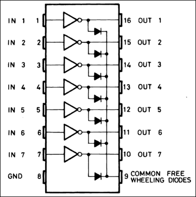
Pins (IN1 to IN7) are input pins and (OUT 1 to OUT 7) are corresponding output pins. COM is given Positive source voltage required for output devices.
LED: RED coloured led is used which emits RED light. Any colours can be used.
Potentiometers: Two potentiometers are used one is for voltage divider for analog input to ADC and another is for controlling brightness of led.
Pin Details of STM32

As we can see the PWM pins are indicated in wave format (~), there are 15 such pins, ADC pins are representd in green colour, 10 ADC pins are there which are used for analog inputs.
Circuit Diagram and Connections

Connections of STM32 with various components are explained as below:
STM32 with Analog Input (ADC)
The potentiometer present at left side of circuit is used as voltage regulator that regulates voltage from the 3.3V pin. The output from the potentiometer i.e. centre pin of potentiometer is connected to the ADC pin (PA4) of STM32.
STM32 with LED
The STM32 PWM output pin (PA9) is connected to the positive pin of LED through a series resistor and a capacitor.
LED with Resistor and Capacitor
A resistor in series and a capacitor in parallel are connected with LED to generate correct Analog wave from PWM output as analog output is not in pure from when generated directly from PWM pin.
STM32 with ULN2003 & ULN2003 with Fan
STM32 PWM output pin (PA8) is connected to the Input pin (IN1) of ULN2003 IC and the corresponding output pin (OUT1) of ULN2003 is connected to negative wire of the DC FAN.
Positive pin of the DC fan is connected to the COM pin of the ULN2003 IC and the external battery (9V DC) is also connected to the same COM pin of the ULN2003 IC. GND pin of ULN2003 is connected to GND pin of STM32 and battery negative is connected to same GND pin.
STM32 with LCD (16x2)
|
LCD Pin No |
LCD Pin Name |
STM32 Pin Name |
|
1 |
Ground (Gnd) |
Ground (G) |
|
2 |
VCC |
5V |
|
3 |
VEE |
Pin from Centre of Potentiometer |
|
4 |
Register Select (RS) |
PB11 |
|
5 |
Read/Write (RW) |
Ground (G) |
|
6 |
Enable (EN) |
PB10 |
|
7 |
Data Bit 0 (DB0) |
No Connection (NC) |
|
8 |
Data Bit 1 (DB1) |
No Connection (NC) |
|
9 |
Data Bit 2 (DB2) |
No Connection (NC) |
|
10 |
Data Bit 3 (DB3) |
No Connection (NC) |
|
11 |
Data Bit 4 (DB4) |
PB0 |
|
12 |
Data Bit 5 (DB5) |
PB1 |
|
13 |
Data Bit 6 (DB6) |
PC13 |
|
14 |
Data Bit 7 (DB7) |
PC14 |
|
15 |
LED Positive |
5V |
|
16 |
LED Negative |
Ground (G) |
A potentiometer on the right side is used to control the contrast of the LCD display. The above table shows the connection between LCD and STM32.
Programming STM32
Like the previous tutorial, we programmed the STM32F103C8 with Arduino IDE through USB port without using FTDI programmer. To learn about programming STM32 with Arduino IDE follow the link. We can proceed programming as like in Arduino. Complete code is given at the end.
In this coding we are going to take a input analog value from ADC pin (PA4) which is connected to centre pin of left potentiometer and then convert the Analog value (0-3.3V) into digital or integer format (0-4095). This digital value is further provided as PWM output to control LED brightness and speed of DC fan. A 16x2 LCD is used to display ADC and mapped value (PWM output value).
First we need to include LCD header file, declare LCD pins and initialize them using below code. Learn more about interfacing LCD with STM32 here.
#include <LiquidCrystal.h>    // include the LCD library
const int rs = PB11, en = PB10, d4 = PB0, d5 = PB1, d6 = PC13, d7 = PC14;  //mention the pin                     names to with LCD is connected to
LiquidCrystal lcd(rs, en, d4, d5, d6, d7);  //Initialize the LCD
Next declare and define the pin names using the pin of STM32
const int analoginput   = PA4;  // Input from potentiometer
const int led           = PA9;  // LED output
const int fan           = PA8;  // fan output
Now inside the setup(), we need to display some messages and clear them after few seconds and specify the INPUT pin and PWM output pins
    lcd.begin(16,2);          //Getting LCD ready
    lcd.clear();          //Clears LCD
    lcd.setCursor(0,0);          //Sets cursor at row0 and column0
    lcd.print("CIRCUIT DIGEST");          //Displays Circuit Digest
    lcd.setCursor(0,1);          //Sets Cursor at column0 and row1
    lcd.print("PWM USING STM32");   //Displays PWM using STM32
    delay(2000);          // Delay Time
    lcd.clear();          // Clears LCD
    pinMode(analoginput, INPUT);          // set pin mode analoginput as INPUT
    pinMode(led, PWM);          // set pin mode led as PWM output
    pinMode(fan, PWM);          // set pin mode fan as PWM output
The Analog input pin (PA4) is set as INPUT by pinMode(analoginput, INPUT), LED pin is set as PWM output by pinMode(led, PWM) and fan pin is set as PWM output by pinMode(fan, PWM). Here the PWM output pins are connected to LED (PA9) and Fan (PA8).
Next in void loop() function, we read the Analog signal from the ADC pin (PA4) and store it in a integer variable that converts analog voltage into digital integer values (0-4095) by using below code int valueadc = analogRead(analoginput);
Important thing to note here is PWM pins that is channels of STM32 has 16-Bit resolution (0-65535) so we need to map that with analog values using map function like below
int result = map(valueadc, 0, 4095, 0, 65535).
If mapping is not used we won’t get full speed of fan or full brightness of LED by varying the potentiometer.
Then we write the PWM output to the LED by using pwmWrite(led, result) and PWM output to fan by using pwmWrite(fan, result) functions.
Finally we display the Analog input value (ADC value) and the output values (PWM values) on LCD display by using following commands
    lcd.setCursor(0,0);          //Sets cursor at row0 and column0
    lcd.print("ADC value= ");           // prints the words “”
    lcd.print(valueadc);          //displays valueadc
    lcd.setCursor(0,1);           //Sets Cursor at column0 and row1
    lcd.print("Output =   ");          //prints the words in ""
    lcd.print(result);            //displays value result
Complete Code with a demonstration Video is given below.
Complete Project Code
#include <LiquidCrystal.h>     // include the LCD library

const int rs = PB11, en = PB10, d4 = PB0, d5 = PB1, d6 = PC13, d7 = PC14;  //mention the pin names to with LCD is connected to

LiquidCrystal lcd(rs, en, d4, d5, d6, d7);  //Initialize the LCD
const int analoginput   = PA4;  // Input from potentiometer

const int led           = PA9;  // LED output

const int fan           = PA8;  // fan output

void setup()

{

    lcd.begin(16,2);     //Getting LCD ready

    lcd.clear();  //Clears LCD

    lcd.setCursor(0,0);  //Sets cursor at row0 and column0

    lcd.print("CIRCUIT DIGEST");   //Displays Circuit Digest

    lcd.setCursor(0,1);          //Sets Cursor at column0 and row1

    lcd.print("PWM USING STM32");   //Displays PWM using STM32

    delay(2000);       // Delay yime

    lcd.clear();       // Clears LCD

    pinMode(analoginput, INPUT);   // set pin mode analoginput as INPUT

    pinMode(led, PWM);           // set pin mode led as PWM output

    pinMode(fan, PWM);            // set pin mode fan as PWM output

}


void loop()
   {

    int valueadc = analogRead(analoginput);     //gets analog value from pot and store in variable,converts to digital

    int result = map(valueadc, 0, 4095, 0, 65535); //maps the (0to4095 into 0to65535) and stores in result variable

    pwmWrite(led, result);           //puts resultin PWM form

    pwmWrite(fan, result);           //puts resultin PWM form

    lcd.setCursor(0,0);             //Sets cursor at row0 and column0

    lcd.print("ADC value= ");           // prints the words in ""

    lcd.print(valueadc);           //displays value

    lcd.setCursor(0,1);             //Sets Cursor at column0 and row1

    lcd.print("Output =   ");          //prints the words in ""

    lcd.print(result);           //displays value result

 }
