

Keeping track of extremely low current levels is often essential when developing or testing low-power devices, especially in the field of embedded systems and battery-operated electronics. For battery-related diagnostics or energy-storage testing, the Building a Lithium Cell Capacity Tester tutorial offers a practical method for measuring cell performance over time. This comprehensive guide shows you how to build a precision digital micro current meter using an STM32 microcontroller and analog components. It is built around an STM32 microcontroller and features an OLED display for real-time readouts. The guide Send/Receive SMS with STM32F103C8 and SIM800C GSM Module provides step-by-step instructions for adding SMS functionality to STM32-based embedded systems. To get started with programming microcontrollers, refer to the analog front end, which is designed to detect small current flows accurately, converting them into voltage levels that the microcontroller can process with high resolution. Whether you're measuring sleep current in a sensor node or characterising a power-efficient circuit, the digital micro ampere meter offers a clear and immediate view of power consumption trends.
Our ampere meter DC digital is designed for ease of use on the workbench, with a focus on readability, stability, and portability. The OLED display provides a crisp output that remains visible under most lighting conditions, while the microcontroller handles signal processing and automatic range detection. Calibration routines ensure measurement consistency across various load conditions. With no need for external tools or complex setups, the device offers a plug-and-play experience for engineers, developers, or hobbyists working with ultra-low-power electronics. Its practical design makes it a useful tool for anyone seeking to analyse power usage with precision and simplicity. Unlike standard ampere meter DC digital solutions, this custom-built digital micro amp meter provides real-time readings on an OLED display with exceptional accuracy across multiple measurement ranges. This precision digital micro current meter delivers laboratory-grade measurements in a portable, battery-powered package.
Watch our complete build guide for this precision digital micro current meter project.
Table of Contents
- Key Features
- Essential Components
- Circuit Diagram and Design Analysis
- └ STM32 Microcontroller Interface
- └ Display and Programming Interfaces
- └ Analog Front-End Design (Based on µCurrent Architecture)
- Custom PCB Design
- PCB Assembly
- 3D Printed Enclosure Design
- Complete Assembly
- Arduino Firmware
- Troubleshooting
- GitHub Repository
Key Features of the Digital Micro Amp Meter
This digital micro ampere meter incorporates professional-grade features that make it suitable for both hobbyist and professional electronics work:
- Powered by the STM32G071KBU microcontroller for fast and accurate signal processing
- 128x64 pixel OLED Display for crisp and readable current measurements
- Multiple Measurement Ranges:
- Nanoamp range: up to 1000 nA
- Microamp range: up to 1000 µA
- Milliamp range: up to 300 mA
- Real-time display updates
- Compact and functional 3D printed Enclosure
- Arduino-based firmware for easy development
- Battery powered with built-in charger
- Soft Power Switch
And to understand high-efficiency energy storage charging, take a look at DIY Modular Cell Grading Machine, a detailed schematic and explanation of a supercapacitor charger circuit.
Essential Components for Building a Digital Micro Ampere Meter
Here is the list of components used to build the digital micro current meter. Exact specifications can be found in the detailed BOM and schematic.
- STM32G071KBU6 Microcontroller
- 128x64 OLED Display Module
- MAX4239AUT Ultra Low Offset/Drift, Low Noise, Precision Operational Amplifiers
- INA333 Micro Power, Zero Drift, Rail-to-Rail Out Instrumentation Amplifier
- LM321 Low Voltage Rail-to-Rail Output Operational Amplifier
- Precision Shunt Resistors (for current sensing in nA, µA, and mA ranges)
- Passive Components, such as resistors and capacitors
- DP3T selector switch for range Selection
- Header Connectors for programming and power interface
- Tactile Switch for reset or mode selection
- USB Type C Connector
- Diodes and Protection Components
- LiPo Battery
- Custom PCB
- 3D Printed Enclosure
- Other Assembly Tools and Consumables
Precision Digital Micro Current Meter Circuit Diagram and Design Analysis
The complete circuit diagram for the Precision Digital Micro Current Meter is shown below. A downloadable PDF version of the schematic is also available in the GitHub repository linked at the end of this article. The complete schematic for this digital micro amp meter is organised into functional blocks for easier understanding.

The schematic has been organised into separate sections based on functionality. This approach makes it easier to understand the role of each part of the circuit in detail. In the following sections, we’ll go through each block individually and explain its purpose and operation. The power section enables versatile operation for this precision digital micro current meter:
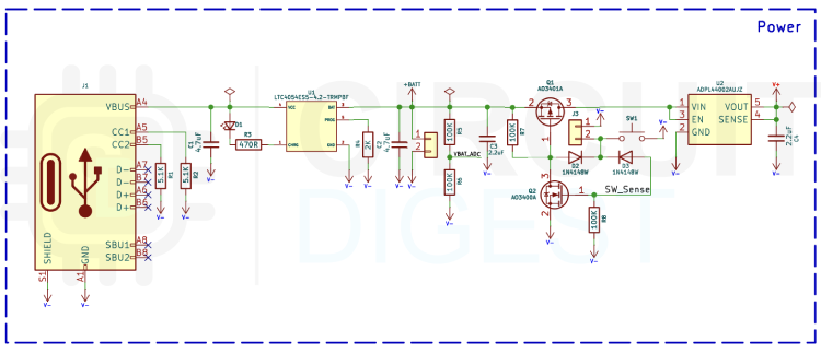
The power section of the circuit is designed to provide a digital micro ampere meter for efficient and reliable operation, with support for USB Type-C input and battery charging. A USB Type C connector is used as the main power input, and pull-down resistors are added to the CC1 and CC2 lines to comply with the USB Type C specification, ensuring compatibility with standard 5V USB sources. For battery management, the LTC4054ES5 is used as a compact linear charger IC, capable of charging a single cell Li ion battery safely and efficiently. To provide regulated voltage to the rest of the circuit, an ADP44002 low dropout (LDO) regulator is used to generate a stable 2.5V supply, suitable for powering both the STM32G071 microcontroller and analog front-end components. A key feature of this section is the soft latch power switch implemented using AO3401 and AO3400 MOSFETs. When the tactile button is pressed, the gate of the P channel AO3401 is pulled low, turning it on and supplying power to the rest of the board. Once powered up, the STM32 configures its PA4 GPIO pin as an input with a pull-up, which keeps the gate of the N-channel AO3400 high, latching the AO3401 in the on state even after the button is released. The same GPIO (PA4) also monitors the button state. When a long press is detected, the microcontroller can reconfigure PA4 as a digital output and drive it low. This action pulls down the gate of the AO3401 through AO3400, turning it off and disconnecting power to the board. Two diodes are used to isolate the control and latch paths, allowing this dual functionality on a single GPIO line.
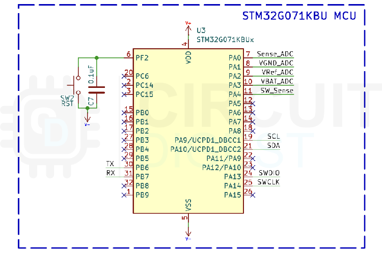
STM32 Microcontroller Interface
The heart of the circuit is the STM32G071KBU microcontroller, which manages all core functions, including data acquisition, display control, and power management. Several analog capable GPIOs are configured to interface with the analog front end and monitor system voltages. Specifically, PA0 is used as the primary ADC input to measure the voltage output from the analog front end, which corresponds to the measured current. PA1 monitors the virtual ground (around 1.25V) used internally in the analog section to maintain a symmetric signal range. PA2 is optionally connected to a precision voltage reference (REF3012AIDBZR) to enable accurate VDDA calculation and calibration. Additionally, PA3 is used to measure battery voltage via a resistor divider, enabling real-time battery monitoring and level indication. The STM32G071KBU serves as the brain of this digital micro ampere meter, managing data acquisition, display control, and system power.
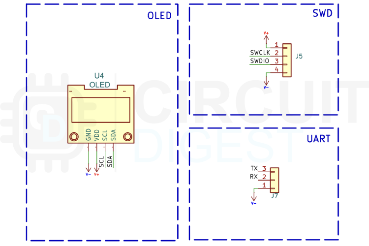
Display and Programming Interfaces
For display communication, the microcontroller uses I2C pins PA9 (SCL) and PA10 (SDA) to interface with a 128x64 OLED display. This setup provides a compact and efficient means of presenting measurement results to the user. To support firmware development and testing, both SWD (Serial Wire Debug) and UART lines are brought out to headers on the PCB, allowing for in-system programming and serial debugging. This arrangement ensures that the microcontroller can be easily programmed, updated, or diagnosed during development or field use. Overall, the MCU section is carefully organised to balance analog accuracy, digital communication, and system control.
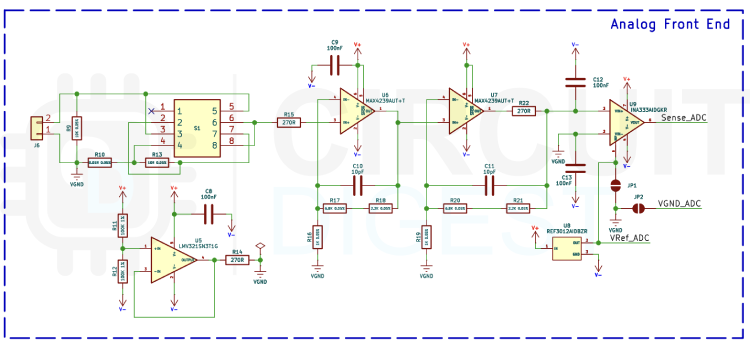
Analog Front-End Design (Based on µCurrent Architecture)
The analog front end of this digital micro amp meter project is based on the well-known µCurrent design by Dave Jones of EEVblog, which is widely recognised for its low burden voltage and high measurement accuracy. At its heart, the system functions as a precision current-to-voltage converter using a set of high-accuracy shunt resistors and ultra-low offset amplifiers. These shunt resistors are configured in a multi-range arrangement to cover nA, µA, and mA current levels, each carefully chosen to keep the burden voltage negligible. Precision is achieved by routing the current through one of these resistors and amplifying the resulting voltage drop using an auto-zero or “chopper” op amp. This architecture allows the system to maintain near-zero output offset and virtually no 1/f noise—two features that are critical for reliably detecting extremely small currents. The key component enabling this precision is the Maxim MAX4239, an auto-zero amplifier with an impressive offset voltage as low as 0.1 µV. Auto-zero amplifiers work by continuously sampling and cancelling their internal offset through a two-phase process controlled by an internal clock. This results in a dynamically corrected output that cancels both DC offset and low-frequency noise, providing a clean signal even under challenging low-current conditions. Though the internal operation of devices like the MAX4239 is proprietary, the benefit is clear: extremely stable and accurate amplification without drift, allowing the analog front end to produce a true zero output when no current is present.
In your implementation, an additional stage has been introduced between the analog front end and the STM32’s ADC: the INA333AIDGKR, a precision instrumentation amplifier. This is a crucial enhancement due to the use of a virtual ground (approximately 1.25V) within the analog signal chain. The virtual ground allows the analog front end to handle bipolar signals centred around mid supply, but it also means the resulting output cannot be directly fed to a single-ended ADC like that of the STM32. The INA333 solves this by amplifying the differential signal with high common-mode rejection, while referencing its output to the same virtual ground. This ensures compatibility with the MCU’s ADC and preserves measurement integrity across all ranges. The output gain of the analog front end is defined by carefully selected precision resistors to ensure consistency and temperature stability. Low ppm, 0.1% tolerance resistors are used to set the gain, typically 100×, which ensures that even nanoamp level currents produce a measurable and amplified voltage. The auto-zero architecture ensures minimal error contribution from the amplifiers themselves, while the use of an instrumentation amplifier like the INA333 adds robustness to the overall signal path, especially when interfacing with microcontroller ADCs operating in a single supply environment.
Custom PCB Design for the Digital Micro Ampere Meter
A custom printed circuit board was designed specifically for this ampere meter DC digital project to ensure compact size and reliable performance. To keep the device compact and practical for everyday use, we designed a custom PCB specifically for this project. The board layout was created using KiCad, and all design files, including schematics and Gerber, are available on the GitHub repository linked at the end of this article. The PCB measures approximately 45mm x 65mm, making it well-suited for both desktop setups and portable applications.
Below are the images showing the top and bottom layers of the PCB:
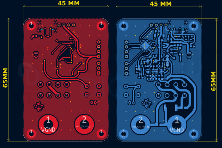
Once the design was reviewed and finalised, we sent the files for fabrication. Critical design considerations for this precision digital micro current meter PCB include:
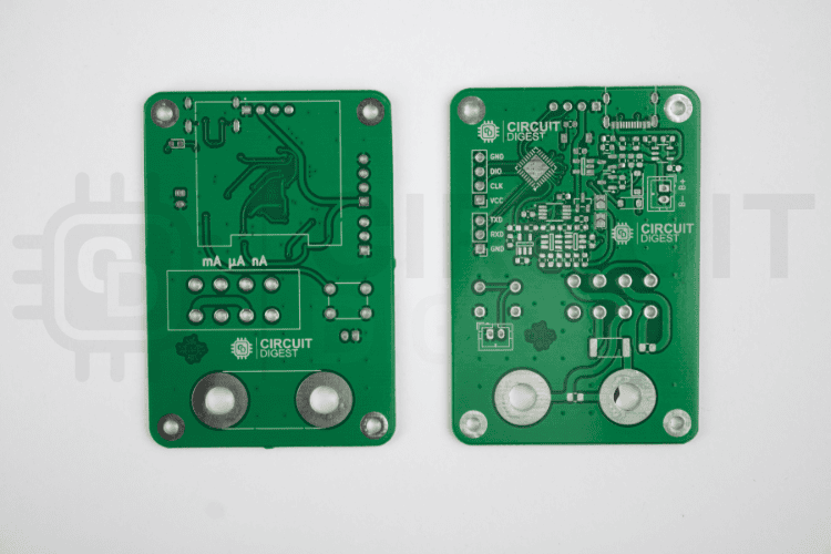
Precision Digital Micro Current Meter PCB Assembly
Assembly of this digital micro ampere meter requires careful attention to detail, particularly when handling sensitive analog components. Assembly began with sorting all components listed in the BOM. We manually placed and soldered each part onto the PCB. For faster or more consistent results, an SMD stencil can be used to apply solder paste, followed by part placement and reflow using either a hot air station or a reflow oven. Below is an image of the fully assembled PCB with all components mounted:
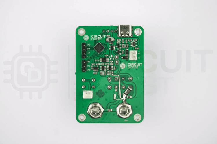
You can see some bodge connections near the inputs, it is because there was a missing connection on the first revision of the PCB. But not to worry, we have already fixed it in the PCB files provided. The completed assembly, including the OLED display module, is shown here:
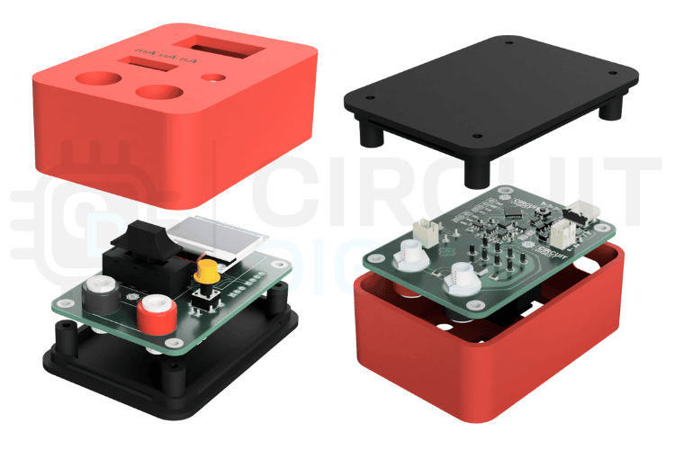
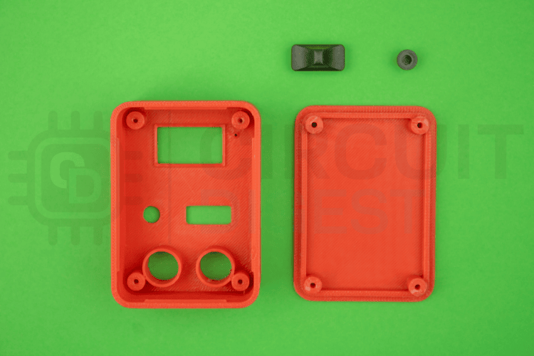
3D Printed Enclosure Design for Portable Operation
To house the circuit neatly and make the device easier to handle, we designed a 3D-printed enclosure. This ensures that the final product is both secure and user-friendly. The STL files for the enclosure can be found in the same GitHub repository as the code and PCB files. If you're new to 3D printing, we've included a link in the article to help you get started.
Here are the 3D printed parts used for the enclosure:
Complete Assembly of the Digital Micro Amp Meter
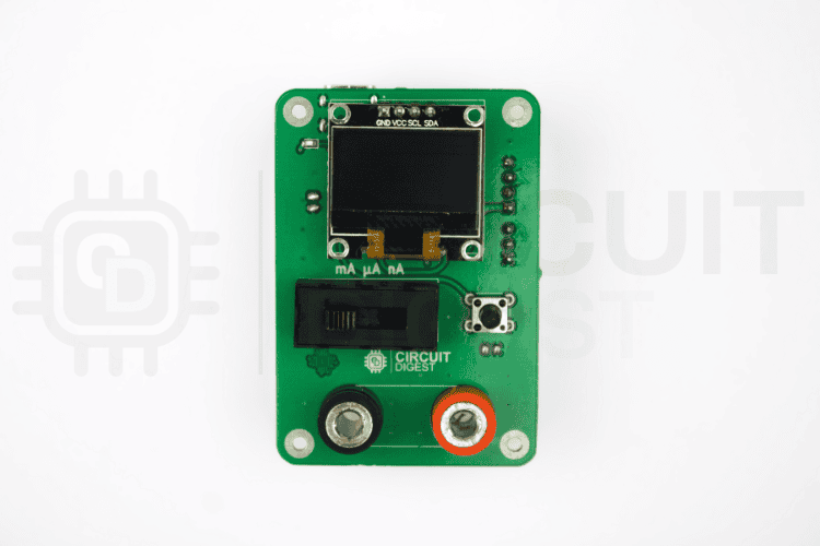
Once all the parts are ready, you can start assembling the Precision Micro Current Meter. To assemble the Precision Micro Current Meter, first insert the tactile switch button cap into the 3D printed frame, followed by the fully assembled PCB. Use the 4mm M2 screws to secure the PCB to the front frame. Later, connect the battery and close the back panel. The back panel will snap fit into the enclosure. After that, you can fix the slide switch cap to the selector switch from the front side. Here is the PCB secured to the 3D printed enclosure.
With all components prepared, the final assembly of this precision digital micro current meter follows a straightforward process:
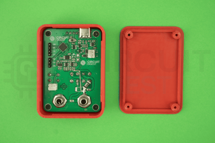
And here is the front side with the OCB secured and switch caps installed.
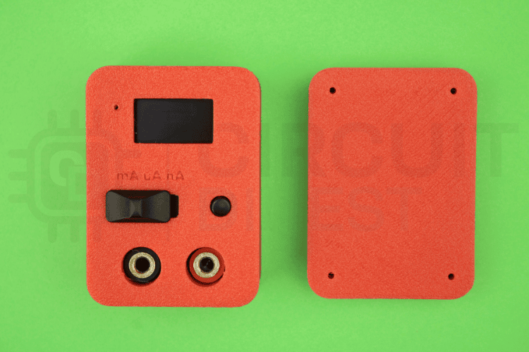
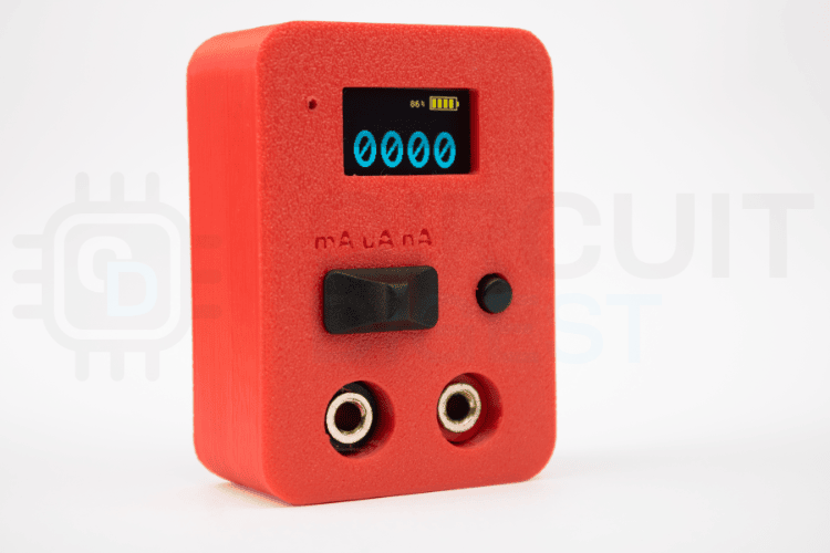
And here is the fully assembled Precision Digital Micro Current Meter.
Arduino Firmware for the STM32-Based Current Meter
The firmware driving this digital micro amp meter is written in Arduino-compatible C++ and programmed onto the STM32G071KBU microcontroller using the Arduino IDE with STM32 board support. With the hardware in place, let’s take a look at the firmware that drives the micro current meter. This project uses an STM32G071KBU microcontroller programmed via the Arduino IDE, along with a 128x64 OLED display using the U8g2 library for rendering text and graphics. The code handles ADC sampling, voltage calculations, display updates, and a soft power-off function triggered by a button. Everything runs within the Arduino framework, making it easy to modify or extend the functionality.
The main sketch contains all the necessary logic. It begins by configuring the ADC to read voltages from key points in the analog front end and converting those into current measurements. It also samples the battery voltage and displays the current reading and battery level in real time on the OLED. To manage power, a soft latch circuit is used. When the button is held and released, the device powers off by pulling the latch pin low. The display updates every 500ms to reflect the latest values, and care is taken to oversample the ADC readings for better resolution.
#include <Wire.h>
#include <HardwareSerial.h>
#include <U8g2lib.h>
// Define our custom HardwareSerial
HardwareSerial MySerial(PB6, PB7);  // TX, RX
U8G2_SSD1306_128X64_NONAME_F_HW_I2C u8g2(U8G2_R0, /* reset=*/U8X8_PIN_NONE);
#define LATCH_PIN PA4
#define NUM_SAMPLES 2
#define SAMPLE_DELAY 10
#define REF_VOLTAGE 1249.3f  // float for precision
#define EMA_ALPHA 0.2f  // Change this to adjust smoothing strength (e.g., 0.1 to 0.3)
volatile bool buttonPressed = false;
volatile bool buttonReleased = false;
volatile unsigned long lastInterruptTime = 0;
unsigned long releaseTime = 0;
const unsigned long debounceDelay = 50;
const unsigned long shutdownDelay = 1000;
unsigned long lastBatteryUpdate = 0;
float batteryVoltage = 0;
int AmpV = 0;
float AmpVF = 0;
int batteryPercent = 0;
The code begins by including the required libraries for I2C communication, serial logging, and OLED display rendering. A custom hardware serial port is initialised on pins PB6 (TX) and PB7 (RX), and the OLED is set up using the U8g2 library in full buffer mode over I2C. A few global constants are defined, such as the analog reference voltage (REF_VOLTAGE), latch pin, and parameters for oversampling. Several global variables are declared to hold button states, battery level, and computed current readings. These will be updated periodically and displayed on the screen.
void buttonISR() {
unsigned long now = millis();
if (now   lastInterruptTime < debounceDelay) return;
if (digitalRead(LATCH_PIN) == LOW) {
  buttonPressed = true;
  buttonReleased = false;
} else {
  if (buttonPressed) {
    buttonReleased = true;
    releaseTime = now;
    delay(500);
    pinMode(LATCH_PIN, OUTPUT);
    digitalWrite(LATCH_PIN, LOW);
    while (1)
      ;
  }
  buttonPressed = false;
}
lastInterruptTime = now;
The buttonISR() interrupt service routine implements the soft latch power-off mechanism for this ampere meter DC digital. It’s triggered on any change to the latch pin. If the button is pressed (detected as LOW), it sets the flag buttonPressed. When the button is released (detected as HIGH), and the press flag was previously set, it confirms the release and begins the shutdown process. A delay is inserted to debounce and allow the user to release the button. Then, it switches the latch pin to output and drives it low to cut power, effectively shutting down the system.
void setup() {
pinMode(LATCH_PIN, INPUT_PULLUP);
attachInterrupt(digitalPinToInterrupt(LATCH_PIN), buttonISR, CHANGE);
MySerial.begin(115200);
MySerial.println("STM32G071 ADC with External Reference (PA2)");
analogReadResolution(12);
u8g2.begin();
}
Inside the setup() function, the latch pin is configured as an input with an internal pull-up, and an interrupt is attached to it. The setup() function performs essential initialisation for this digital micro ampere meter. Serial output is initialised at 115200 baud for debugging. The ADC resolution is set to 12 bits, which matches the native resolution of the STM32 ADC. Finally, the OLED is initialised with u8g2.begin().
void loop() {
unsigned long now = millis();
if (now   lastBatteryUpdate > 500) {
  float vdda = measureVDDA();
  batteryVoltage = measureInputVoltage(PA3, vdda) * 2.0f;
  float Vref = measureInputVoltage(PA1, vdda);
  float ampVoltage = measureInputVoltage(PA0, vdda);
  //AmpV = ((int)((ampVoltage   Vref) / 2.0f))   3;
  //float error_percent = 4.77f;
  //AmpV = (int)(((ampVoltage   Vref) / 2.0f) * (1.0f   error_percent / 100.0f)) 3;
  float raw = ((ampVoltage   Vref) / 1.0f);
  float offset = 6.0f;
  float error_percent = 0.0f;
  //AmpV = (int)((raw   offset) * (1.0f   error_percent / 100.0f));
  AmpVF = (raw  * (1.0f   error_percent / 100.0f)  offset);
  AmpV = (int)AmpVF;
  batteryPercent = batteryLevelPercent((int)batteryVoltage);
  MySerial.print("VDDA: "); MySerial.print(vdda);
  MySerial.print(" mV, Vref: "); MySerial.print(Vref);
  MySerial.print(" mV, PA2: "); MySerial.print(measureInputVoltage(PA2, vdda));
  MySerial.print(" mV, Amp: "); MySerial.println(AmpV);
  lastBatteryUpdate = now;
  u8g2.clearBuffer();
  u8g2.setFont(u8g2_font_5x8_tr);
  int iconX = 96, iconY = 0, iconW = 28, iconH = 12;
  char batteryPercentStr[6];
  itoa(batteryPercent, batteryPercentStr, 10);
  strcat(batteryPercentStr, "%");
  u8g2.drawStr(iconX   20, iconY + 10, batteryPercentStr);
  drawBatteryIconWithBars(iconX, iconY, iconW, iconH, batteryPercent);
  char AmpStr[7];
  if (AmpV < 0) {
    sprintf(AmpStr, " %04d", abs(AmpV));
  } else {
    sprintf(AmpStr, " %04d", AmpV);
  }
  u8g2.setFont(u8g2_font_inb33_mn);
  u8g2.drawStr( 10, 62, AmpStr);
  u8g2.sendBuffer();
}
}
The loop() function checks if 500ms have passed since the last update using millis(). If so, it begins a fresh set of measurements. First, measureVDDA() is called to determine the actual VDDA based on a known reference. Then, measureInputVoltage(PA3, vdda) is used to sample the battery voltage, and it is scaled by 2x due to a resistive voltage divider. The current sense reference is read from PA1, and the measured signal is read from PA0. The raw difference is scaled and adjusted with an offset to compensate for baseline drift or frontend error. Battery percentage is calculated using the batteryLevelPercent() function. The display is then cleared and updated with the current reading, along with the battery status.
float measureVDDA() {
uint32_t sum = 0;
for (int i = 0; i < NUM_SAMPLES; i++) {
  sum += oversampledADC(PA1);
  delayMicroseconds(SAMPLE_DELAY);
}
float adcAvg = (float)sum / NUM_SAMPLES;
float vdda = (REF_VOLTAGE * 65535.0f) / adcAvg;
return vdda;
}
The measureVDDA() function reads the ADC value from the external precision reference connected to PA1. It averages NUM_SAMPLES oversampled readings and calculates the actual VDDA using the known value of the reference (1.2493V). This approach improves accuracy by correcting for supply voltage variation, which directly affects ADC readings.
float measureInputVoltage(uint32_t pin, float vdda) {
uint32_t sum = 0;
for (int i = 0; i < NUM_SAMPLES; i++) {
  sum += oversampledADC(pin);
  delayMicroseconds(SAMPLE_DELAY);
}
float adcAvg = (float)sum / NUM_SAMPLES;
float voltage = (adcAvg * vdda) / 65535.0f;
return voltage;
}
The measureInputVoltage() function takes any analog input pin and the current VDDA value, performs NUM_SAMPLES oversampled ADC reads, and returns the actual voltage at the pin. This function is used for measuring the battery input, the internal reference, and the signal from the analog front end. It relies on oversampledADC() to get a high-resolution result.
uint32_t oversampledADC(uint32_t pin) {
uint32_t sum = 0;
const int oversample_count = 256;  // 2^(2 × (16   12)) = 256
for (int i = 0; i < oversample_count; i++) {
  sum += analogRead(pin);  // 12 bit reading
  delayMicroseconds(SAMPLE_DELAY);   // optional: allow settling
}
// Average and scale to 16 bit range
uint32_t avg = sum / oversample_count;
uint32_t adc16 = avg << 4;  // 12 bit to 16 bit shift (multiply by 16)
// Ignore 3 LSBs
const int ignore_lsb = 4;
adc16 = (adc16 >> ignore_lsb) << ignore_lsb;
return adc16;
}
The oversampledADC() function implements 256x oversampling to extend the 12-bit native resolution of the STM32 ADC to approximately 16 bits. It sums 256 readings, averages them, and left shifts by 4 bits to scale it to a 16-bit range. It then discards the least significant 3 bits to reduce noise. This method gives more stable readings, especially important for small signal measurements like nanoamp currents. The oversampledADC() function is critical for achieving high measurement resolution in this precision digital micro current meter.
int batteryLevelPercent(int v_bat) {
int percent = (v_bat   3000) * 100 / (4200   3000);
if (percent > 100) percent = 100;
if (percent < 0) percent = 0;
return percent;
}
The batteryLevelPercent() function converts a voltage in millivolts to a percentage between 0 and 100. The input is linearly mapped between 3000 mV (0%) and 4200 mV (100%). Any value below or above these limits is clamped. This function helps present an intuitive battery status to the user.
void drawBatteryIconWithBars(int x, int y, int w, int h, int percent) {
u8g2.drawFrame(x, y, w, h);
u8g2.drawBox(x + w, y + h / 3, 2, h / 3);
int numBars = 4;
int barSpacing = 2;
int barWidth = (w   6   (numBars   1) * barSpacing) / numBars;
int barHeight = h   4;
int barsToDraw = (percent + 24) / 25;
for (int i = 0; i < barsToDraw; i++) {
  int bx = x + 2 + i * (barWidth + barSpacing);
  u8g2.drawBox(bx, y + 2, barWidth, barHeight);
}
}
The drawBatteryIconWithBars() function draws a rectangular battery icon on the top right of the OLED. A small terminal is added on the right side, and up to four bars are filled based on the battery percentage. The number of bars is calculated by rounding up every 25%. This visual representation complements the numeric value and gives the user quick insight into the battery condition. This graphical representation complements the numeric percentage value, providing an at-a-glance battery status for users of this digital micro amp meter.
Troubleshooting Guide
If you encounter issues with your ampere meter DC digital, refer to these common problems and solutions:
| Problem | Possible Cause | Solution |
| Device won't power on | Battery discharged or disconnected | Charge via USB-C or check battery connection |
| Unstable or noisy readings | Long measurement leads or EMI interference | Shorten leads, increase EMA_ALPHA for more filtering |
| OLED display blank | I2C connection issue or display failure | Check solder joints on PA9/PA10, verify display functionality |
| Can't upload firmware | SWD connection problem or wrong board selected | Verify SWD connections, select STM32G071 in Arduino IDE |
| Battery won't charge | Faulty USB cable or LTC4054 issue | Try different USB-C cable, check charger IC soldering |
Applications for the Digital Micro Ampere Meter
This precision digital micro current meter serves numerous applications in electronics development and testing:
- In terms of IoT device development, the focus will be on the characterisation of various operational characteristics, including, but not limited to, sleep currents, active currents, and transmission bursts of wireless sensor nodes, and other ESP32/ESP8266 projects, as well as LoRa devices.
- For battery life estimation, current consumption profiles will need to be collected and analysed to estimate the expected battery life for portable products.
- Power optimisation will require an evaluation of the code that consumes the most power and optimisation of the firmware for extended battery operation in embedded systems.
- Microcontroller sleep mode analysis will confirm that the microcontroller's ability to transition to low-power modes properly, and additionally, retention current will be measured in various sleep states.
- Evaluating micro energy harvesters to provide enough current for continuous operation.
- Circuit troubleshooting will identify an abnormal increase in current that could point to a failure in circuitry, such as open or short circuit conditions.
- Educational projects will demonstrate how to understand and calculate current draw, optimise energy usage, and create low-power products.
- BLE (Bluetooth low energy) devices, wireless modules, and other wireless devices will require evaluation of their advertising, connection, and sleep current consumption.
Frequently Asked Questions About Digital Micro Ampere Meters
⇥ What is a Precision Digital Microcurrent Meter used for?
It is a precision digital microcurrent meter that measures very low currents from nanoamperes to milliamperes. This meter will be indispensable in testing battery-operated IoT devices, measuring sleep current in microcontrollers, characterising low-power sensors, optimising energy-efficient circuits, and debugging issues related to power consumption in embedded systems. These meters provide real-time current readings with high accuracy across multiple ranges.
⇥ How accurate are digital micro-ampere meters?
This digital micro ampere meter achieves ±0.1% accuracy using auto-zero amplifiers like the MAX4239 (0.1µV offset) and precision instrumentation amplifiers. The 16-bit effective resolution from oversampled ADC readings allows for reliable measurements down to 1 nanoampere. For better accuracy, the device definitely needs to be calibrated to appropriate specifications, the intensity and accuracy of the sensor input maintained at best performance, a stable source of power be supplied, and the environment remain as quiet as possible.
⇥ Is it possible to create a digital micro amp meter for use at home?
This article explains how to make a high-quality digital micro amp meter from home using basic electronic knowledge. The Project requires knowledge of soldering SMD components along with all components needed to complete the build according to the Bill of Materials (BOM). In addition, you will need to design your own PCB as well as find and print an enclosure using a 3D printer. The GitHub repository contains design files, firmware, and an assembly guide for this Project.
⇥ How do I calibrate my digital micro ampere meter?
Calibration consists of the measurement of known current sources and firmware offset adjustments. Precision current sources or stable resistor-voltage combinations for each range are required. The displayed value is measured, the error is calculated, and the firmware offset is updated accordingly. The REF3012 voltage reference allows the calculation of VDDA needed in ADC conversion. Regular calibration with certified standards ensures that this measurement is accurate over a long period.
⇥ What is the battery life of the portable current meter?
Ultimately, how long the meter will run is based on usage patterns and the capacity of the battery. If you use a standard 400mAh LiPo battery, the meter can run for quite a few hours while in operation. The soft latch Power switch will help to extend the battery life by allowing you to completely cut off power to the meter when not in use. The battery converter operates efficiently due to the LDO regulator that delivers 2.5V. The LTC4054 chip allows the battery to be recharged using CVS technology. To have longer runs in the Field, you can use a battery with a higher capacity/mAh battery.
GitHub Repository
Visit the GitHub repository to download the source code, make modifications, and deploy the project effortlessly.


Conclusion: Building Your Own Professional Current Measurement Tool
This guide has shown you how to construct a Precision Digital Micro current Meter. A laboratory-grade digital microcurrent meter has been built using inexpensive components and tools. This meter combines the power and versatility of an STM32 Processor with an Auto-Zero Amplifier and Precision Instrumentation to produce a version of digital micro ampere meter (uA) that is capable of competing with many commercially available products that cost significantly more than this product. This Digital Micro-ampere Meter has three range settings: Nano Amps (nA), Micro Amps (uA), Milliamps (mA). It is very flexible in multiple applications, from measuring sleep currents of IoT Devices to understanding sensor power consumption characteristics. This device is useful for Electronics Engineers to maximise the Battery Life of their Designs; Makers Building Prototypes of Low Security Devices; and Students Learning the Basic Concepts of Precision Measurement Technology. This digital micro amp meter project not only gives you valuable experience in Advanced Analog Design, Microcontroller Programming (STM32), and Professional PCB Manufacturing, but also serves to build your confidence and improve your understanding of the technology.
This tutorial was created by the CircuitDigest engineering team. Our experts focus on creating practical, hands-on tutorials that help makers and engineers master Raspberry Pi projects, Arduino projects, STM32 projects and IoT development projects.
I hope you liked this article and learned something new from it. If you have any doubts, you can ask in the comments below or use our CircuitDigest forum for a detailed discussion.
STM32 Microcontroller Projects
Explore practical STM32 projects that explain circuits, code, and real-world applications in simple, beginner-friendly tutorials given below.

Programming the STM32F103C8 Board using the USB Port
Learn how to program the STM32F103C8 (Blue Pill) board directly through its USB port. This guide explains how to install the Maple bootloader, set up the Arduino IDE, and upload code without using an external programmer.

How to use I2C Communication in STM32 Microcontroller
In this tutorial, we will use one Arduino board with the Blue Pill board, that is the STM32F103C8 and will communicate with the Arduino board using the I2C bus.

Programming STM32F103C8 using Keil uVision & STM32CubeMX
Quick guide to programming the STM32F103C8 using STM32CubeMX and Keil uVision, covering setup, code generation, and uploading with ST-LINK.
Complete Project Code
/*
*
* Author: Jobit Joseph
*
*/
#include <Wire.h>
#include <HardwareSerial.h>
#include <U8g2lib.h>
#define LATCH_PIN PA4
#define NUM_SAMPLES 2
#define SAMPLE_DELAY 10
#define REF_VOLTAGE 1249.3f  // float for precision
// Define our custom HardwareSerial
HardwareSerial MySerial(PB6, PB7);  // TX, RX
U8G2_SSD1306_128X64_NONAME_F_HW_I2C u8g2(U8G2_R0, /* reset=*/U8X8_PIN_NONE);
volatile bool buttonPressed = false;
volatile bool buttonReleased = false;
volatile unsigned long lastInterruptTime = 0;
unsigned long releaseTime = 0;
const unsigned long debounceDelay = 50;
const unsigned long shutdownDelay = 1000;
unsigned long lastBatteryUpdate = 0;
float batteryVoltage = 0;
int AmpV = 0;
float AmpVF = 0;
int batteryPercent = 0;
void buttonISR() {
 unsigned long now = millis();
 if (now - lastInterruptTime < debounceDelay) return;
 if (digitalRead(LATCH_PIN) == LOW) {
   buttonPressed = true;
   buttonReleased = false;
 } else {
   if (buttonPressed) {
     buttonReleased = true;
     releaseTime = now;
     delay(500);
     pinMode(LATCH_PIN, OUTPUT);
     digitalWrite(LATCH_PIN, LOW);
     while (1)
       ;
   }
   buttonPressed = false;
 }
 lastInterruptTime = now;
}
void setup() {
 pinMode(LATCH_PIN, INPUT_PULLUP);
 attachInterrupt(digitalPinToInterrupt(LATCH_PIN), buttonISR, CHANGE);
 MySerial.begin(115200);
 MySerial.println("STM32G071 ADC with External Reference (PA2)");
 analogReadResolution(12);
 u8g2.begin();
}
void loop() {
 unsigned long now = millis();
 if (now - lastBatteryUpdate > 500) {
   float vdda = measureVDDA();
   batteryVoltage = measureInputVoltage(PA3, vdda) * 2.0f;
   float Vref = measureInputVoltage(PA1, vdda);
   float ampVoltage = measureInputVoltage(PA0, vdda);
   //AmpV = ((int)((ampVoltage - Vref) / 2.0f)) - 3;
   //float error_percent = 4.77f;
   //AmpV = (int)(((ampVoltage - Vref) / 2.0f) * (1.0f - error_percent / 100.0f))-3;
   float raw = ((ampVoltage - Vref) / 1.0f);
   float offset = 6.0f;
   float error_percent = 0.0f;
   //AmpV = (int)((raw - offset) * (1.0f - error_percent / 100.0f));
   AmpVF = (raw  * (1.0f - error_percent / 100.0f)- offset);
   AmpV = (int)AmpVF;
   batteryPercent = batteryLevelPercent((int)batteryVoltage);
   MySerial.print("VDDA: "); MySerial.print(vdda);
   MySerial.print(" mV, Vref: "); MySerial.print(Vref);
   MySerial.print(" mV, PA2: "); MySerial.print(measureInputVoltage(PA2, vdda));
   MySerial.print(" mV, Amp: "); MySerial.println(AmpV);
   lastBatteryUpdate = now;
   u8g2.clearBuffer();
   u8g2.setFont(u8g2_font_5x8_tr);
   int iconX = 96, iconY = 0, iconW = 28, iconH = 12;
   char batteryPercentStr[6];
   itoa(batteryPercent, batteryPercentStr, 10);
   strcat(batteryPercentStr, "%");
   u8g2.drawStr(iconX - 20, iconY + 10, batteryPercentStr);
   drawBatteryIconWithBars(iconX, iconY, iconW, iconH, batteryPercent);
   char AmpStr[7];
   if (AmpV < 0) {
     sprintf(AmpStr, "-%04d", abs(AmpV));
   } else {
     sprintf(AmpStr, " %04d", AmpV);
   }
   u8g2.setFont(u8g2_font_inb33_mn);
   u8g2.drawStr(-10, 62, AmpStr);
   u8g2.sendBuffer();
 }
}
float measureVDDA() {
 uint32_t sum = 0;
 for (int i = 0; i < NUM_SAMPLES; i++) {
   sum += oversampledADC(PA1);
   delayMicroseconds(SAMPLE_DELAY);
 }
 float adcAvg = (float)sum / NUM_SAMPLES;
 float vdda = (REF_VOLTAGE * 65535.0f) / adcAvg;
 return vdda;
}
float measureInputVoltage(uint32_t pin, float vdda) {
 uint32_t sum = 0;
 for (int i = 0; i < NUM_SAMPLES; i++) {
   sum += oversampledADC(pin);
   delayMicroseconds(SAMPLE_DELAY);
 }
 float adcAvg = (float)sum / NUM_SAMPLES;
 float voltage = (adcAvg * vdda) / 65535.0f;
 return voltage;
}
uint32_t oversampledADC(uint32_t pin) {
 uint32_t sum = 0;
 const int oversample_count = 256;  // 2^(2 × (16 - 12)) = 256
 for (int i = 0; i < oversample_count; i++) {
   sum += analogRead(pin);  // 12-bit reading
   delayMicroseconds(SAMPLE_DELAY);   // optional: allow settling
 }
 // Average and scale to 16-bit range
 uint32_t avg = sum / oversample_count;
 uint32_t adc16 = avg << 4;  // 12-bit to 16-bit shift (multiply by 16)
 // Ignore 3 LSBs
 const int ignore_lsb = 4;
 adc16 = (adc16 >> ignore_lsb) << ignore_lsb;
 return adc16;
}
int batteryLevelPercent(int v_bat) {
 int percent = (v_bat - 3000) * 100 / (4200 - 3000);
 if (percent > 100) percent = 100;
 if (percent < 0) percent = 0;
 return percent;
}
void drawBatteryIconWithBars(int x, int y, int w, int h, int percent) {
 u8g2.drawFrame(x, y, w, h);
 u8g2.drawBox(x + w, y + h / 3, 2, h / 3);
 int numBars = 4;
 int barSpacing = 2;
 int barWidth = (w - 6 - (numBars - 1) * barSpacing) / numBars;
 int barHeight = h - 4;
 int barsToDraw = (percent + 24) / 25;
 for (int i = 0; i < barsToDraw; i++) {
   int bx = x + 2 + i * (barWidth + barSpacing);
   u8g2.drawBox(bx, y + 2, barWidth, barHeight);
 }
}
