
STM32 Microcontrollers which uses ARM Cortex M architecture is now becoming popular and are used in many applications because of its feature, cost and performance. We have programmed STM32F103C8 using the Arduino IDE in our previous tutorials. Programming STM32 with Arduino IDE is simple, as there are lots of libraries available for various sensors to perform any task, we just need to add those libraries in the program. This is an easy procedure and you may not get into deep learning about the ARM processors. So now we are getting into the next level of programming called ARM programming. By this we can, not only improve our structure of the code but can also save memory space by not using unnecessary libraries.
STMicroelectronics introduced a tool called STM32Cube MX, which generates basic code according to the peripherals and the selected STM32 board. So we don’t need to worry about coding for basic drivers and peripherals. Further this generated code can be used in Keil uVision for editing according to requirement. And finally the code is burned into STM32 using ST-Link programmer from STMicroelectronics.
In this tutorial we will learn how to program STM32F103C8 using Keil uVision & STM32CubeMX by doing a simple project of interfacing a push button and LED with the STM32F103C8 Blue Pill board. We will generate the code using STM32Cube MX then edit & upload the code to STM32F103C8 using Keil uVision. Before getting into detail, we will first learn about ST-LINK programmer and STM32CubeMX software tool.
ST-LINK V2
The ST-LINK/V2 is an in-circuit debugger and programmer for the STM8 and STM32 microcontroller families. We can upload code to STM32F103C8 and other STM8 & STM32 microcontrollers using this this ST-LINK. The single wire interface module (SWIM) and JTAG/serial wire debugging (SWD) interfaces are used to communicate with any STM8 or STM32 microcontroller located on an application board. As STM32 applications use the USB full-speed interface to communicate with Atollic, IAR, Keil or TASKING integrated development environments, so we can use this hardware to program the STM 8 & STM32 microcontrollers.
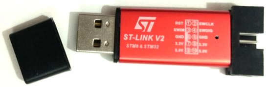
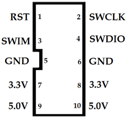
Above is the image of ST-LINK V2 dongle from STMicroelectronics that supports the full range of STM32 SWD debugging interface, a simple 4-wire interface (including power), fast and stable. It is available in a variety of colours. The body is made out of aluminium alloy. It has a blue LED indication as it is used to observe the working state of the ST-LINK. The pin names are clearly marked on the shell as we can see in the above image. It can be interfaced with the Keil software where the program can be flashed to the STM32 microcontrollers. So let’s see in this tutorial how this ST-LINK programmer can be used to program STM32 microcontroller. Below image shows the pins of the ST-LINK V2 module.
Note: When connecting ST-Link with the computer for first time .We need device driver to be installed. Device drivers can be found in this link according to your operating system.
STM32CubeMX
STM32CubeMX tool is part of STMicroelectronics STMCube .This software tool makes the development easy by reducing development effort, time and cost. STM32Cube includes STM32CubeMX which is a graphical software configuration tool that allows the generation of C initialization code using graphical wizards. That code can be used in various development environments like keil uVision, GCC, IAR etc. You can download this tool from the following link.
STM32CubeMX has following features
- Pin out-conflict solver
- A clock-tree setting helper
- A power-consumption calculator
- An utility performing MCU peripheral configuration like GPIO pins, USART etc
- An utility performing MCU peripheral configuration for middleware stacks like USB, TCP/IP etc
Materials Required
Hardware
- STM32F103C8 Blue Pill board
- ST-LINK V2
- Push Button
- LED
- Breadboard
- Jumper Wires
Software
Circuit Diagram and Connections
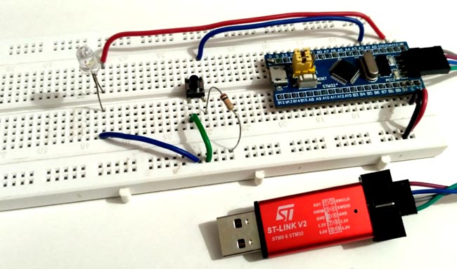
Below is the circuit diagram to simply connect an LED with STM32 board using a pushbutton.

Connection between ST-LINK V2 & STM32F103C8
Here the STM32 Blue Pill board is powered from the ST-LINK which is connected to the computer’s USB port. So we need not to power the STM32 separately. The table below shows the connection between ST-Link and Blue pill board.
|
STM32F103C8 |
ST-Link V2 |
|
GND |
GND |
|
SWCLK |
SWCLK |
|
SWDIO |
SWDIO |
|
3V3 |
3.3V |
LED & Push Button
The LED is used to indicate the output from Blue Pill board when a push button is pressed. LED’s anode is connected to the pin PC13 of the Blue Pill board and cathode is grounded.
A push button is connected to provide input to the pin PA1 of Blue Pill board. We must also use a pull up resistor of value 10k because the pin might float without any input when the button is released. One end of the push button is connected to ground and other end to pin PA1 & a pull up resistor of 10k is also connected to 3.3V of Blue Pill board.
Creating and burning a program into STM32 using Keil uVision and ST-Link
Step 1:- First install all the device drivers for ST-LINK V2, software tools STM32Cube MX & Keil uVision and install necessary packages for STM32F103C8.
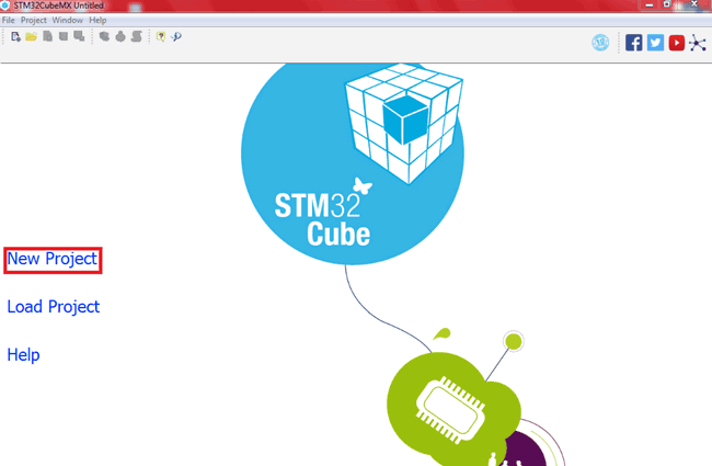
Step 2:- Second step is Open >> STM32Cube MX
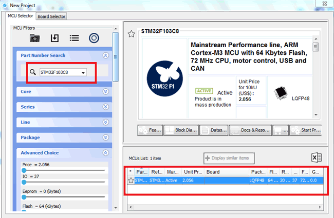
Step 3:- Then Click on New Project
Step 4:- After that search & select our microcontroller STM32F103C8
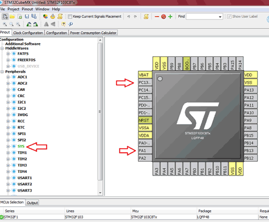
Step 5:- Now the pin-out sketch of STM32F103C8 appears, here we can set the pin configurations. We can also select our pins in the peripherals section according to our project.
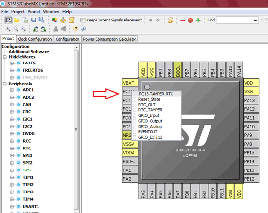
Step 6:- You can also click on the pin directly and a list appears, now select the required pin configuration.
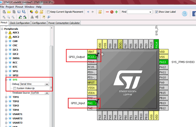
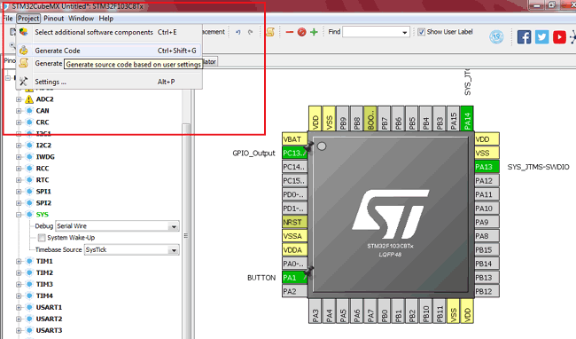
Step 7:- For our project we have selected PA1 as GPIO INPUT, PC13 as GPIO OUTPUT & SYS debug as SERIAL WIRE, here only we connect the ST-LINK SWCLK & SWDIO pins. The selected & configured pins appear in GREEN colour. You can note that in below image.
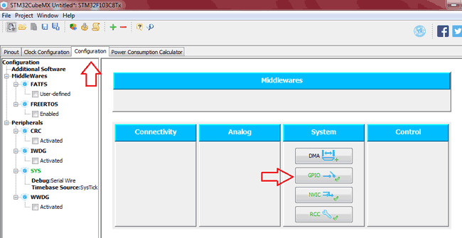
Step 8:- Next under the Configuration tab, select GPIO to set GPIO pin configurations for the pins we have selected.
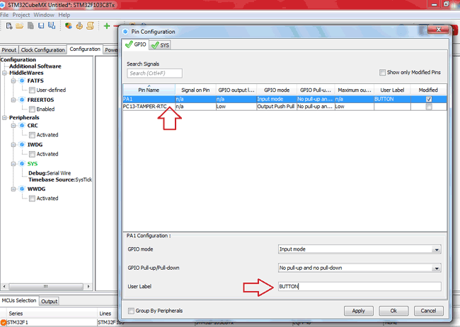
Step 9:- Next in this pin configuration box we can configure User Label for pins we are using, that is user defined pin names.
Step 10:- After that click on Project >> Generate Code.
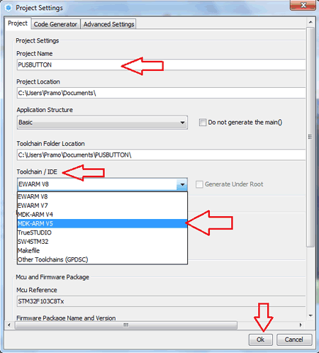
Step 11:- Now the project settings dialog box appears. In this box choose your project name and location and select the development environment .We are using Keil so select MDK-ARMv5 as IDE.
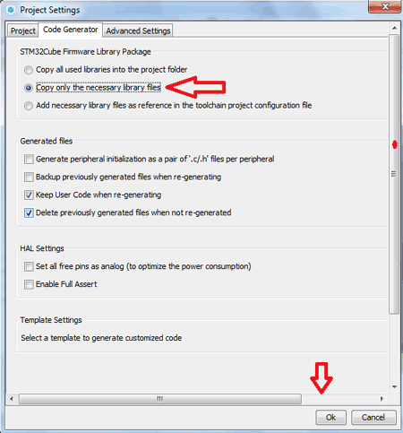
Step 12:- Next under Code Generator tab, select Copy only the necessary library files and then click OK.
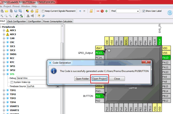
Step 13:- Now the code generation dialog box appears. Select Open Project to open project automatically the generated code in Keil uvsion.
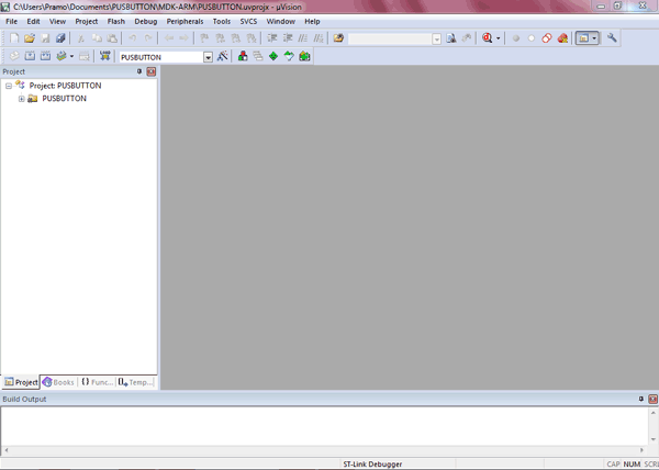
Step 14:- Now the Keil uVision tool opens with our generated code in STM32CubeMx with the same project name with necessary library and codes that are configured for the pins we selected.
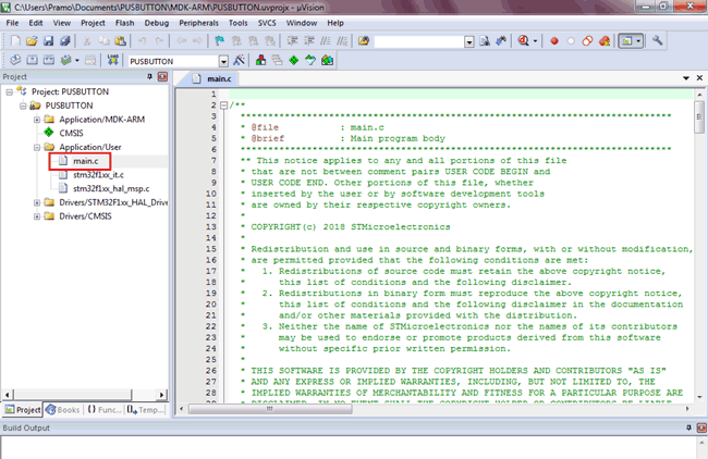
Step 15:- Now we just need to include the logic to perform some action at the output LED (pin PC13 ) when the button is pressed and released at the GPIO input (pin PA1). So select our main.c program to include some codes.
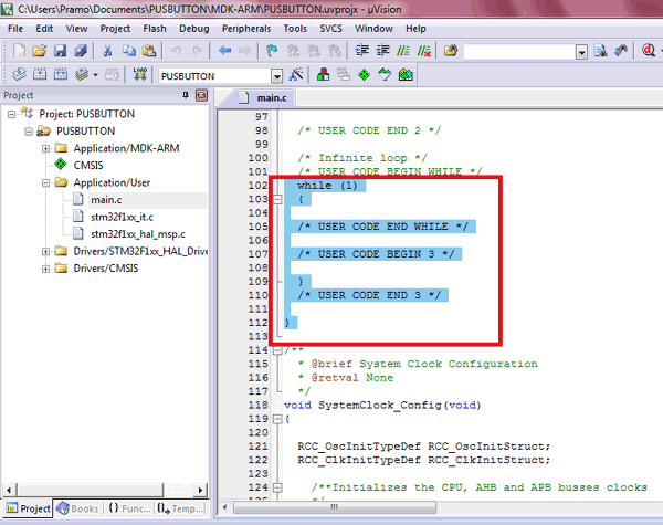
Step 16:- Now add the code in the while(1) loop, see the below image where I highlighted that section to run the code continuously.
while (1)
{
  if(HAL_GPIO_ReadPin(BUTN_GPIO_Port,BUTN_Pin)==0) //=> DETECTS Button is Pressed
{
    HAL_GPIO_WritePin(LEDOUT_GPIO_Port,LEDOUT_Pin,1); //To make output high when button pressesd
}

else
{
    HAL_GPIO_WritePin(LEDOUT_GPIO_Port,LEDOUT_Pin,0); //To make output Low when button de pressed
}
}
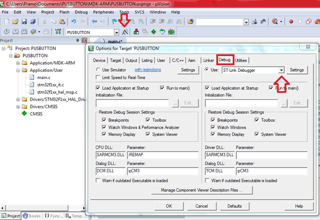
Step 17:- After finish editing the code, click the Options for Target icon under the debug tab select ST-LINK Debugger
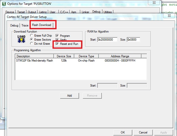
Also, click on Settings button and then under Flash Download tab tick the Reset and Run check box and click ‘ok’.
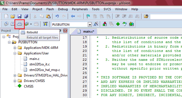
Step 18:- Now click on Rebuild icon to rebuild all target files.
Step 19:- Now you can plug in the ST-LINK to computer with the circuit connections ready and click on the DOWNLOAD icon or press F8 to flash the STM32F103C8 with the code you have generated and edited.
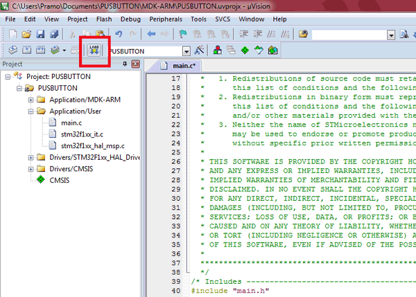
Step 20:- You can notice the flashing indication at the bottom of the keil uVision window.
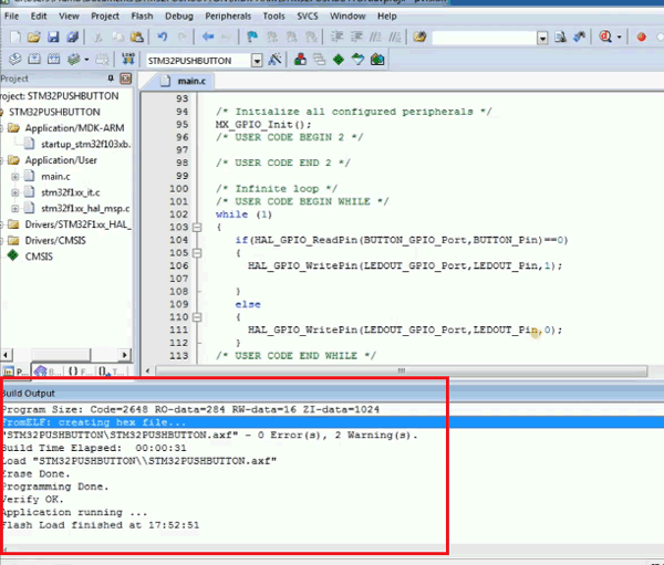
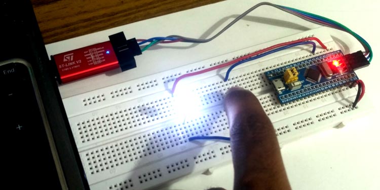
Output of Keil Programmed STM32 Board
Now when we press the push button, LED turn On and when we release it, the LED turns Off.
Program
The main part which we have added in the generated program is shown below. This below code needs to be included in while(1) of main.c program generated by the STM32CubeMX. You can go back to Step 15 to step 17 to learn how it should be added in main.c program.
while (1)
{
  if(HAL_GPIO_ReadPin(BUTN_GPIO_Port,BUTN_Pin)==0) //=> DETECTS Button is Pressed
{
    HAL_GPIO_WritePin(LEDOUT_GPIO_Port,LEDOUT_Pin,1); //To make output high when button pressesd
}

else
{
    HAL_GPIO_WritePin(LEDOUT_GPIO_Port,LEDOUT_Pin,0); //To make output Low when button de pressed
}
}
Complete process of creating and uploading project into STM32 board is also explained in the Video given at the end. Also the complete code of main.c file is given below including the above given code.
Further, you can find our complete set of STM32 projects here.
Complete Project Code
/**
  ******************************************************************************
  * @file           : main.c
  * @brief          : Main program body
  ******************************************************************************
  ** This notice applies to any and all portions of this file
  * that are not between comment pairs USER CODE BEGIN and
  * USER CODE END. Other portions of this file, whether
  * inserted by the user or by software development tools
  * are owned by their respective copyright owners.
  *
  * COPYRIGHT(c) 2018 STMicroelectronics
  *
  * Redistribution and use in source and binary forms, with or without modification,
  * are permitted provided that the following conditions are met:
  *   1. Redistributions of source code must retain the above copyright notice,
  *      this list of conditions and the following disclaimer.
  *   2. Redistributions in binary form must reproduce the above copyright notice,
  *      this list of conditions and the following disclaimer in the documentation
  *      and/or other materials provided with the distribution.
  *   3. Neither the name of STMicroelectronics nor the names of its contributors
  *      may be used to endorse or promote products derived from this software
  *      without specific prior written permission.
  *
  * THIS SOFTWARE IS PROVIDED BY THE COPYRIGHT HOLDERS AND CONTRIBUTORS "AS IS"
  * AND ANY EXPRESS OR IMPLIED WARRANTIES, INCLUDING, BUT NOT LIMITED TO, THE
  * IMPLIED WARRANTIES OF MERCHANTABILITY AND FITNESS FOR A PARTICULAR PURPOSE ARE
  * DISCLAIMED. IN NO EVENT SHALL THE COPYRIGHT HOLDER OR CONTRIBUTORS BE LIABLE
  * FOR ANY DIRECT, INDIRECT, INCIDENTAL, SPECIAL, EXEMPLARY, OR CONSEQUENTIAL
  * DAMAGES (INCLUDING, BUT NOT LIMITED TO, PROCUREMENT OF SUBSTITUTE GOODS OR
  * SERVICES; LOSS OF USE, DATA, OR PROFITS; OR BUSINESS INTERRUPTION) HOWEVER
  * CAUSED AND ON ANY THEORY OF LIABILITY, WHETHER IN CONTRACT, STRICT LIABILITY,
  * OR TORT (INCLUDING NEGLIGENCE OR OTHERWISE) ARISING IN ANY WAY OUT OF THE USE
  * OF THIS SOFTWARE, EVEN IF ADVISED OF THE POSSIBILITY OF SUCH DAMAGE.
  *
  ******************************************************************************
  */
/* Includes ------------------------------------------------------------------*/
#include "main.h"
#include "stm32f1xx_hal.h"

/* USER CODE BEGIN Includes */
/* USER CODE END Includes */
/* Private variables ---------------------------------------------------------*/
/* USER CODE BEGIN PV */
/* Private variables ---------------------------------------------------------*/
/* USER CODE END PV */

/* Private function prototypes -----------------------------------------------*/
void SystemClock_Config(void);
static void MX_GPIO_Init(void);

/* USER CODE BEGIN PFP */
/* Private function prototypes -----------------------------------------------*/

/* USER CODE END PFP */
/* USER CODE BEGIN 0 */
/* USER CODE END 0 */

/**
  * @brief  The application entry point.
  *
  * @retval None
  */
int main(void)
{
  /* USER CODE BEGIN 1 */
  /* USER CODE END 1 */
  /* MCU Configuration----------------------------------------------------------*/

  /* Reset of all peripherals, Initializes the Flash interface and the Systick. */
  HAL_Init();

  /* USER CODE BEGIN Init */
  /* USER CODE END Init */
  /* Configure the system clock */
  SystemClock_Config();

  /* USER CODE BEGIN SysInit */
  /* USER CODE END SysInit */

  /* Initialize all configured peripherals */
  MX_GPIO_Init();
  /* USER CODE BEGIN 2 */
  /* USER CODE END 2 */

  /* Infinite loop */
  /* USER CODE BEGIN WHILE */
  while (1)
  {
     if(HAL_GPIO_ReadPin(BUTN_GPIO_Port,BUTN_Pin)==0) //=> Button is Pressed

{

              HAL_GPIO_WritePin(LEDOUT_GPIO_Port,LEDOUT_Pin,1);
}

else //=>Button is released

{
              HAL_GPIO_WritePin(LEDOUT_GPIO_Port,LEDOUT_Pin,0);
}
  /* USER CODE END WHILE */
  /* USER CODE BEGIN 3 */

  }
  /* USER CODE END 3 */

}

/**
  * @brief System Clock Configuration
  * @retval None
  */
void SystemClock_Config(void)
{

  RCC_OscInitTypeDef RCC_OscInitStruct;
  RCC_ClkInitTypeDef RCC_ClkInitStruct;

    /**Initializes the CPU, AHB and APB busses clocks
    */
  RCC_OscInitStruct.OscillatorType = RCC_OSCILLATORTYPE_HSI;
  RCC_OscInitStruct.HSIState = RCC_HSI_ON;
  RCC_OscInitStruct.HSICalibrationValue = 16;
  RCC_OscInitStruct.PLL.PLLState = RCC_PLL_NONE;
  if (HAL_RCC_OscConfig(&RCC_OscInitStruct) != HAL_OK)
  {
    _Error_Handler(__FILE__, __LINE__);
  }

    /**Initializes the CPU, AHB and APB busses clocks
    */
  RCC_ClkInitStruct.ClockType = RCC_CLOCKTYPE_HCLK|RCC_CLOCKTYPE_SYSCLK
                              |RCC_CLOCKTYPE_PCLK1|RCC_CLOCKTYPE_PCLK2;
  RCC_ClkInitStruct.SYSCLKSource = RCC_SYSCLKSOURCE_HSI;
  RCC_ClkInitStruct.AHBCLKDivider = RCC_SYSCLK_DIV1;
  RCC_ClkInitStruct.APB1CLKDivider = RCC_HCLK_DIV1;
  RCC_ClkInitStruct.APB2CLKDivider = RCC_HCLK_DIV1;

  if (HAL_RCC_ClockConfig(&RCC_ClkInitStruct, FLASH_LATENCY_0) != HAL_OK)
  {
    _Error_Handler(__FILE__, __LINE__);
  }

    /**Configure the Systick interrupt time
    */
  HAL_SYSTICK_Config(HAL_RCC_GetHCLKFreq()/1000);

    /**Configure the Systick
    */
  HAL_SYSTICK_CLKSourceConfig(SYSTICK_CLKSOURCE_HCLK);

  /* SysTick_IRQn interrupt configuration */
  HAL_NVIC_SetPriority(SysTick_IRQn, 0, 0);
}

/** Configure pins as
        * Analog
        * Input
        * Output
        * EVENT_OUT
        * EXTI
*/
static void MX_GPIO_Init(void)
{

  GPIO_InitTypeDef GPIO_InitStruct;

  /* GPIO Ports Clock Enable */
  __HAL_RCC_GPIOC_CLK_ENABLE();
  __HAL_RCC_GPIOA_CLK_ENABLE();

  /*Configure GPIO pin Output Level */
  HAL_GPIO_WritePin(LEDOUT_GPIO_Port, LEDOUT_Pin, GPIO_PIN_RESET);

  /*Configure GPIO pin : LEDOUT_Pin */
  GPIO_InitStruct.Pin = LEDOUT_Pin;
  GPIO_InitStruct.Mode = GPIO_MODE_OUTPUT_PP;
  GPIO_InitStruct.Pull = GPIO_NOPULL;
  GPIO_InitStruct.Speed = GPIO_SPEED_FREQ_LOW;
  HAL_GPIO_Init(LEDOUT_GPIO_Port, &GPIO_InitStruct);

  /*Configure GPIO pin : BUTN_Pin */
  GPIO_InitStruct.Pin = BUTN_Pin;
  GPIO_InitStruct.Mode = GPIO_MODE_INPUT;
  GPIO_InitStruct.Pull = GPIO_NOPULL;
  HAL_GPIO_Init(BUTN_GPIO_Port, &GPIO_InitStruct);

}

/* USER CODE BEGIN 4 */

/* USER CODE END 4 */

/**
  * @brief  This function is executed in case of error occurrence.
  * @param  file: The file name as string.
  * @param  line: The line in file as a number.
  * @retval None
  */
void _Error_Handler(char *file, int line)
{
  /* USER CODE BEGIN Error_Handler_Debug */
  /* User can add his own implementation to report the HAL error return state */
  while(1)
  {
if(HAL_GPIO_ReadPin(BUTN_GPIO_Port,BUTN_Pin)==0) //=> DETECTS Button is Pressed
    {
    HAL_GPIO_WritePin(LEDOUT_GPIO_Port,LEDOUT_Pin,1); //To make output high when button pressesd
    }
    else
    {
    HAL_GPIO_WritePin(LEDOUT_GPIO_Port,LEDOUT_Pin,0); //To make output Low when button de pressed
    }
  }
  /* USER CODE END Error_Handler_Debug */
}

#ifdef  USE_FULL_ASSERT
/**
  * @brief  Reports the name of the source file and the source line number
  *         where the assert_param error has occurred.
  * @param  file: pointer to the source file name
  * @param  line: assert_param error line source number
  * @retval None
  */
void assert_failed(uint8_t* file, uint32_t line)
{
  /* USER CODE BEGIN 6 */
  /* User can add his own implementation to report the file name and line number,
     tex: printf("Wrong parameters value: file %s on line %d\r\n", file, line) */
  /* USER CODE END 6 */
}
#endif /* USE_FULL_ASSERT */

/**
  * @}
  */

/**
  * @}
  */

/************************ (C) COPYRIGHT STMicroelectronics *****END OF FILE****/
Comments
i am trying to put the blue pill board in the debug mode but it only flashes the bluepill board.Can we debug this board or not ?Is there some settings have to be done or somethingelse. please help
ok the StmF1 series clone boards are cheap, the software tools are free, lots of versatility, BUT, using a 32 bit processor to blink a LED in only 17 steps. Ironically 17 variants of the boot loader if you want to use the USB connection to program. IMHO a pig in a poke. Likely makes more "cents" to spend time with the ESP devices with their integration with the lowly Arduino infrastructure.

Thank you for this awesome post, I was wondering if I could use the usb-ttl programmer we use with blue pill when programming arduino when using its native arm tools? also instead of the stlink can one use kitProg from cypress, I only have those two options and I really want to start learning as I await stlink order. Any guidance is highly welcomed