
In our previous tutorials, we have learned about SPI and I2C communication between two Arduino boards. In this tutorial we will replace one Arduino board with the Blue Pill board that is STM32F103C8 and will communicate with the Arduino board using I2C bus.
STM32 has more features than Arduino board. So it would be great to learn about communication between STM32 and Arduino by using SPI & I2C bus. In this tutorial, we will use I2C bus for communication between Arduino and STM32F103C8, and will learn about SPI bus in next tutorial. To know more about STM32 board, check other STM32 projects.
STM32F103C8 I2C Overview
Comparing I2C (Inter Integrated Circuits) in STM32F103C8 Blue Pill board with Arduino Uno, then we will see that Arduino has ATMEGA328 microcontroller in it, and STM32F103C8 has ARM Cortex- M3 in it. STM32 has Two I2C bus while Arduino Uno only has one I2C bus and STM32 is faster than Arduino.
To learn more about I2C communication, refer our previous articles
- How to use I2C in Arduino: Communication between two Arduino Boards
- I2C Communication with PIC Microcontroller PIC16F877
- Interfacing 16X2 LCD with ESP32 using I2C
- I2C communication with MSP430 Launchpad
- Interfacing LCD with NodeMCU without using I2C
- How to handle multi communications (I2C SPI UART) in single program of arduino
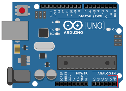
I2C pins in STM32F103C8
SDA: PB7 or PB9, PB11.
SCL: PB6 or PB8, PB10.

I2C pins in Arduino
SDA: A4 pin
SCL: A5 pin
Components Required
- STM32F103C8
- Arduino Uno
- LED (2-Nos)
- Push Button (2-Nos)
- Resistors (4-Nos [10k-2 & 2.2k-2])
- Breadboard
- Connecting Wires
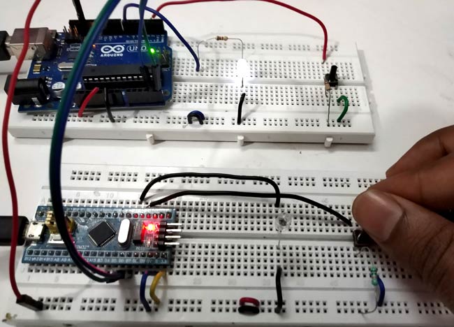
Circuit Diagram and Connections

The following table shows the connection between STM32 Blue Pill and Arduino Uno for using I2C bus. It requires only two wires.
|
STM32F103C8 |
Arduino |
Pin Description |
|
B7 |
A4 |
SDA |
|
B6 |
A5 |
SCL |
|
GND |
GND |
Ground |
Important
- Don’t forget to connect the Arduino GND and STM32F103C8 GND together.
- Then connect a Pull down resistor of 10k to the push button pins of both the board separately.
In this STM32 I2C tutorial we will configure the STM32F103C8 as Master and Arduino as Slave. Both boards are attached with an LED & a push button separately.
To demonstrate I2C communication in STM32, we control the master STM32 LED by using slave Arduino push button value and control slave Arduino LED by using master STM32F103C8 push button value. These values are sent via I2C communication bus.
I2C Programming in STM32
The programming is similar to the Arduino code. The same <wire.h> library is used in programming STM32F103C8. It can be programmed using USB port without using FTDI programmer, to learn more about programming STM32 with Arduino IDE follow the link.
This tutorial has two programs one for master STM32 and other for slave Arduino. Complete programs for both the sides are given at the end of this project with a demonstration Video.
Master STM32 Programming Explanation
In Master STM32 let’s see what’s happening:
1. First of all we need to include the Wire library and softwire library for using I2C communication functions in STM32F103C8.
#include<Wire.h>
#include<SoftWire.h>
2. In void setup()
- We Start Serial Communication at Baud Rate 9600.
Serial.begin(9600);
- Next we start the I2C communication at pin (B6,B7)
Wire.begin();
3. In Void loop()
- First we get the data from the Slave Arduino so we use requestFrom() with the slave address 8 and we request one byte.
Wire.requestFrom(8,1);
The received value is read using Wire.read()
byte a = Wire.read();
- Depending upon the received value from slave the Master LED is turned ON or OFF by using digitalwrite at pin PA1 and also serial print is used to print value in serial monitor
if (a==1)
      {
      digitalWrite(LED,HIGH);
      Serial.println("Master LED ON");
      }
    else
      {
      digitalWrite(LED,LOW);
      Serial.println("Master LED OFF");
      }
- Next we need to read the status of the pin PA0 that is the master STM32 push button.
int pinvalue = digitalRead(buttonpin);
- Next send the pin value according to the logic, so we use if condition and then begin the transmission with slave arduino with 8 as address and then write the value according to the push button input value.
if(pinvalue==HIGH)
    {
      x=1;

    }
  else
   {
      x=0;

    }

Wire.beginTransmission(8);
Wire.write(x);
Wire.endTransmission();
Slave Arduino Programming Explanation
1. First of all we need to include the Wire library for using I2C communication functions.
#include<Wire.h>
2. In void setup()
- We Start Serial Communication at Baud Rate 9600.
Serial.begin(9600);
- Next start the I2C communication at pin (A4, A5) with slave address as 8. Here it is important to specify the slave address.
Wire.begin(8);
Next we need to call Wire.onReceive function when Slave receives value from master and Wire.onRequest function call when Master request value from Slave.
Wire.onReceive(receiveEvent); Wire.onRequest(requestEvent);
3. Next we have two functions one for request event and one for receive event
For request Event
When Master STM32 request value from slave this function will execute. This function does take input value from the Slave Arduino push button and send a byte (1 or 0) to Master STM32 according to push button value by using Wire.write().
void requestEvent()
  {
  int value = digitalRead(buttonpin);

  if (value == HIGH)
{
    x=1;
  }
  else
  {
   x=0;
  }
  Wire.write(x);
 }
For Receive Event
When Master sends data to slave with slave address (8), this function will execute. This function reads the received value from master and store in a variable of type byte and then use if logic to turn slave LED ON or OFF depending upon the value received. If received value is 1 then LED turns ON and for 0 LED turns OFF.
void receiveEvent (int howMany)
 {
  byte a = Wire.read();

  if (a == 1)

 {
   digitalWrite(LED,HIGH);
   Serial.println("Slave LED ON");

  }
  else
  {
    digitalWrite(LED,LOW);
    Serial.println("Slave LED OFF");
  }
  delay(500);
}
Output
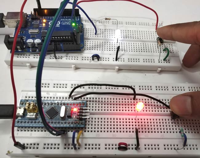
1. When we press the push button at Master STM32, the LED connected to Slave Ardiono turns ON (White).
2. Now when we press the push button at Slave side, the LED connected to Master turns ON (Red) and when button is released LED turns OFF.
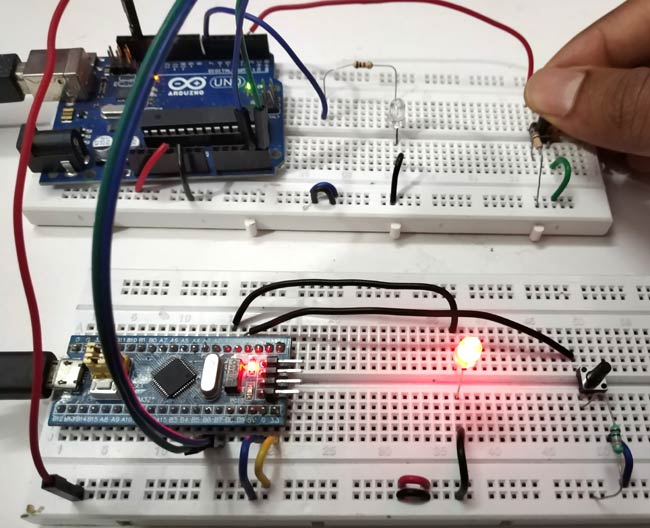
3. When both the push buttons pressed simultanewolsy, then both the LEDs glow at the same time, and remains ON until the buttons are pressed
So this is how I2C communication takes place in STM32. Now you can interface any I2C sensor with STM32 board.
The complete coding for Master STM32 and Slave Arduino is given below with a demonstration video
Complete Project Code
Master STM32 Code
//I2C Master Code (STM32F103C8)

//I2C Communication between STM32 and Arduino

//Circuit Digest
#include<Wire.h>

#include<SoftWire.h>                   //Library for I2C Communication functions
#define LED PA1

#define buttonpin PA0
int x = 0;
void setup()

{


  Serial.begin(9600);                  //Begins Serial Communication at 9600 baud rate

  pinMode(buttonpin,INPUT);            //Sets pin PA0 as input

  pinMode(LED,OUTPUT);                 //Sets PA1 as Output

  Wire.begin();                        //Begins I2C communication at pin (B6,B7)

}

void loop()

{

    Wire.requestFrom(8,1);               // request  bytes from slave arduino(8)

    byte a = Wire.read();                // receive a byte from the slave arduino and store in variable a


    if (a==1)                            //Logic to turn Master LED ON (if received value is 1) or OFF (if received value is 0)

      {

      digitalWrite(LED,HIGH);

      Serial.println("Master LED ON");

      }

    else

      {

      digitalWrite(LED,LOW);

      Serial.println("Master LED OFF");

      }

  {


   int pinvalue = digitalRead(buttonpin);    //Reads the status of the pin PA0


  if(pinvalue==HIGH)                         //Logic for Setting x value (To be sent to slave Arduino) depending upon inuput from pin PA0

    {

      x=1;

    }


  else

   {

      x=0;

   }


  Wire.beginTransmission(8);                 // starts transmit to device (8-Slave Arduino Address)

  Wire.write(x);                             // sends the value x to Slave

  Wire.endTransmission();                    // stop transmitting

  delay(500);

  }

}


Slave Arduino Code
//I2C Slave Code (Arduino)

//I2C Communication between STM32 and Arduino

//Circuit Digest

#include<Wire.h>                             //Library for I2C Communication functions
#define LED 7

#define buttonpin 2

byte x =0;

void setup()
{

  Serial.begin(9600);                        //Begins Serial Communication at 9600 baud rate

  pinMode(LED,OUTPUT);                       //Sets pin 7 as output

  Wire.begin(8);                             // join i2c bus with its slave Address as 8 at pin (A4,A5)

  Wire.onReceive(receiveEvent);              //Function call when Slave Arduino receives value from master STM32

  Wire.onRequest(requestEvent);              //Function call when Master STM32 request value from Slave Arduino

}

void loop()

{

  delay(100);

}
void receiveEvent (int howMany)              //This Function is called when Slave Arduino receives value from master STM32

{

  byte a = Wire.read();                      //Used to read value received from master STM32 and store in variable a


  if (a == 1)                                //Logic to turn Slave LED ON (if received value is 1) or OFF (if received value is 0)

  {

   digitalWrite(LED,HIGH);

   Serial.println("Slave LED ON");


  }

  else

  {

    digitalWrite(LED,LOW);

    Serial.println("Slave LED OFF");

  }

  delay(500);


}
void requestEvent()                            //This Function is called when Master STM32 wants value from slave Arduino

{

  int value = digitalRead(buttonpin);          //Reads the status of the pin 2

  if (value == HIGH)                           //Logic to set the value of x to send to master depending upon input at pin 2

  {

    x=1;

  }

  else

  {

    x=0;

  }

  Wire.write(x);                             // sends one byte of x value to master STM32

}


}
Comments
It is almost the same you have to use the two wire method and declare your I2C like
TwoWire myWire(MY_SCL_PIN, MY_SDA_PIN, MY_SPEED);
what happen to i2c pull up resistors in this circuit.pleaaase!!
Hi everyone, in this example there aren't the pull-up resistor on I2C bus and a shift level device.
The STM32 works at 3.3V and Arduino works at 5V.
I had some problems with this communication (I2C) and different type of voltage level.
I think it is necessary to put a shift level on I2C bus between Arduino board and STM32 board.
Bye

I didn't see on this article or your other communication articles how to use the second I2C bus (I2C-2) in the same program as the first bus I2C-1 for the Blue Pill. Would you please explain and/or provide code to show how to do it? Thank you.