
MSP430 is a powerful platform provided by Texas Instruments for embedded projects, its versatile nature has made it to find ways into many applications and the phase is still going. If you have been following our MSP430 tutorials then you would have noticed we have already covered wide a range of tutorials on this microcontroller starting from the very basics. Since now, we have covered the basics we can get into more interesting stuff like the communication portal.
In the vast system of embedded applications, no microcontroller can perform all the activities by itself. At some stage of time it has to communicate to other devices to share information, there are many different types of communication protocols to share these information’s, but the most used ones are USART, IIC, SPI and CAN. Each communication protocol has its own advantage and disadvantage. Let’s focus on the I2C part for now since that is what we are going to learn in this tutorial.
What is I2C Communication Protocol?
The term IIC stands for “Inter Integrated Circuits”. It is normally denoted as I2C or I squared C or even as 2-wire interface protocol (TWI) at some places but it all means the same. I2C is a synchronous communication protocol meaning, both the devices that are sharing the information must share a common clock signal. It has only two wires to share information out of which one is used for the cock signal and the other is used for sending and receiving data.
How I2C Communication works?
I2C communication was first introduced by Phillips. As said earlier it has two wires, these two wires will be connected across two devices. Here one device is called a master and the other device is called as slave. Communication should and will always occur between two a Master and a Slave. The advantage of I2C communication is that more than one slave can be connected to a Master.
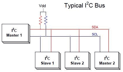
The complete communication takes place through these two wires namely, Serial Clock (SCL) and Serial Data (SDA).
Serial Clock (SCL): Shares the clock signal generated by the master with the slave
Serial Data (SDA): Sends the data to and from between the Master and slave.
At any given time only the master will be able to initiate the communication. Since there is more than one slave in the bus, the master has to refer to each slave using a different address. When addressed only the slave with that particular address will reply back with the information while the others keep quit. This way we can use the same bus to communicate with multiple devices.
The voltage levels of I2C are not predefined. I2C communication is flexible, means the device which is powered by 5v volt, can use 5v for I2C and the 3.3v devices can use 3v for I2C communication. But what if two devices which are running on different voltages, need to communicate using I2C? A 5V I2C bus can’t be connected with 3.3V device. In this case voltage shifters are used to match the voltage levels between two I2C buses.
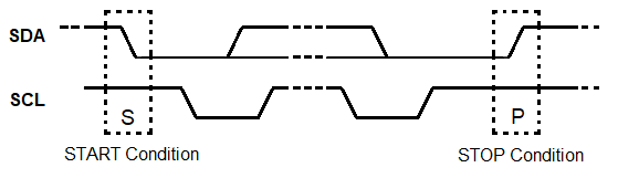
There are some set of conditions which frame a transaction. Initialization of transmission begins with a falling edge of SDA, which is defined as ‘START’ condition in below diagram where master leaves SCL high while setting SDA low.
As shown in the above diagram below,
The falling edge of SDA is the hardware trigger for the START condition. After this all devices on the same bus go into listening mode.
In the same manner, rising edge of SDA stops the transmission which is shown as ‘STOP’ condition in above diagram, where the master leaves SCL high and also releases SDA to go HIGH. So rising edge of SDA stops the transmission.

R/W bit indicates the direction of transmission of following bytes, if it is HIGH means the slave will transmit and if it is low means the master will transmit.
Each bit is transmitted on each clock cycle, so it takes 8 clock cycles to transmit a byte. After each byte either sent or received, ninth clock cycle is held for the ACK/NACK (acknowledged/not acknowledged). This ACK bit is generated by either slave or master depending upon the situation. For ACK bit, SDA is set to low by master or slave at 9th clock cycle. So it is low it considered as ACK otherwise NACK.

Where to use I2C communication?
I2C communication is used only for short distance communication. It is certainly reliable to an extent since it has a synchronised clock pulse to make it smart. This protocol is mainly used to communicate with sensor or other devices which has to send information to a master. It is very handy when a microcontroller has to communicate with many other slave modules using a minimum of only wires. If you are looking for a long range communication you should try RS232 and if you are looking for more reliable communication you should try the SPI protocol.
I2C in MSP430: Controlling AD5171 Digital Potentiometer
Energia IDE is one of the easiest software to program our MSP430. It is same as Arduino IDE. You can learn more about Getting started with MSP430 using Energia IDE here.
So, to use I2C in Energia IDE we have to just include wire.h header file. Pin declaration (SDA and SCL) is inside the wire library, so we not need to declare in setup function.
Sample examples can be found in Example menu of the IDE. One of the examples is explained below:
This example shows how to control a Analog Devices AD5171 Digital Potentiometer which communicates via the I2C synchronous serial protocol. Using MSP's I2C Wire Library, the digital pot will step through 64 levels of resistance, fading an LED.
First, we will include the library responsible for i2c communication i.e. wire library
#include <Wire.h>
In setup function, we will initiate the wire library by .begin() function.
void setup() {
  Wire.begin();
}
Then initialize a variable val to store values of potentiometer
byte val = 0;
In loop function, we will start transmission to the i2c slave device (in this case Digital potentiometer IC) by specifying the device address which is given in the datasheet of the IC.
void loop() {
Wire.beginTransmission(44); // transmit to device #44 (0x2c)
Subsequently, queue bytes i.e. data you want to send to the IC for transmission with the write() function.
 Wire.write(byte(0x00));            // sends instruction byte
 Wire.write(val);             // sends potentiometer value byte
Then transmit them by calling endTransmission().
 Wire.endTransmission();     // stop transmitting
  val++;        // increment value
  if (val == 64) {       // if reached 64th position (max)
    val = 0;    // start over from lowest value
  }
  delay(500);
}
Complete Project Code
#include <Wire.h>

byte val = 0;
void setup() {

  Wire.begin();

}
void loop() {

Wire.beginTransmission(44); // transmit to device #44 (0x2c)

Wire.write(byte(0x00));            // sends instruction byte

Wire.write(val);             // sends potentiometer value byte

Wire.endTransmission();     // stop transmitting

  val++;        // increment value

  if (val == 64) {       // if reached 64th position (max)

    val = 0;    // start over from lowest value

  }

  delay(500);

}
