
Keypad interfacing with 8051 microcontroller represents one of the fundamental skills for embedded systems developers. Matrix keypads are an input device found in calculators, security systems, ATMs, and various industrial control panels. Keypads are widely used input devices in various electronics and embedded projects. They are used to take inputs in the form of numbers and letters, and feed the same into the system for further processing. In this tutorial, we are going to interface a 4x4 matrix keypad with an 8051 microcontroller. This collection of tutorials demonstrates interfacing 4×4 matrix keypads with Arduino, various microcontrollers and development boards, including Keypad Interfacing with Arduino Uno, and Interfacing I2C LCD and 4x4 Keypad with Raspberry Pi Zero W. The guides cover hardware wiring, row-column scanning techniques, and software implementation for detecting key presses. Several examples also integrate 16×2 LCDs, including I2C variants, to display input or computation results, as seen in the Arduino calculator project. Together, these resources provide practical insights into embedded system design, input handling, and efficient microcontroller programming for real-world applications.
Table of Contents
What is a 4x4 Matrix Keypad?
Before we 4x4 matrix keypad interface with the microcontroller, first we need to understand how it works. Matrix keypad consists of a set of Push buttons, which are interconnected. Like in our case, we are using a 4X4 matrix keypad, in which there are 4 push buttons in each of four rows. And the terminals of the push buttons are connected according to the diagram. In the first row, one terminal of all 4 push buttons is connected, and another terminal of the 4 push buttons represents each of the 4 columns. The same goes for each row. So we are getting 8 terminals to connect with a microcontroller. Unlike individual switches that require one GPIO pin each, the matrix configuration allows interfacing of a keyboard with an 8051 microcontroller using only 8 pins total—significantly optimising port usage for embedded applications.
Internal Structure of 4X4 Matrix Keypad
If you want to properly interface to the 4x4 matrix keypad using an 8051 microcontroller pinout, it is important to know the terminal pinout of the keypad. Each keypad has 8 terminals - four for rows (R1-R4) and four for columns (C1-C4). In this matrix, the push buttons are wired such that:
- In each row, one terminal of all four buttons is wired to a common row line
- The other terminal of each button is wired to its column line
- When you press a button, an electrical connection occurs between the corresponding row and column
- By using a matrix arrangement, you can interface the keypad with an 8051 microcontroller by following a systematic row-column scanning process.
Components Required for Keypad Interfacing with 8051 Microcontroller
| Component | Specification |
|---|---|
| Microcontroller | 8051 (AT89S52/AT89C51) |
| Keypad Type | 4x4 Matrix (16 keys) |
| GPIO Pins Required | 8 pins (1 complete port) |
| Programming Language | Embedded C / Assembly |
| Display Interface | 16x2 LCD (recommended) |
Circuit Diagram: Keypad Interfacing with 8051 Microcontroller (AT89S52)

First, we need to interface an LCD module to display the data which will be fed through the KEYPAD, so please go through the “LCD Interfacing with 8051 Microcontroller” article before interfacing the KEYPAD.
Pin Connection Guide: 4x4 Matrix Keypad with 8051 Microcontroller Programming
For proper keypad interfacing with the 8051 microcontroller matrix configuration, follow this systematic connection pattern:
As shown in the above circuit diagram, to interface the Keypad, we need to connect 8 terminals of the keypad to any port (8 pins) of the microcontroller. Like we have connected keypad terminals to Port 1 of the 8051. Whenever any button is pressed, we need to get the location of the button, which means the corresponding ROW and COLUMN no. Once we get the location of the button, we can print the character accordingly.
| Keypad Terminal | 8051 Port Pin | Function |
| Row 1 (R1) | P1.4 | Output |
| Row 2 (R2) | P1.5 | Output |
| Row 3 (R3) | P1.6 | Output |
| Row 4 (R4) | P1.7 | Output |
| Column 1 (C1) | P1.0 | Input |
| Column 2 (C2) | P1.1 | Input |
| Column 3 (C3) | P1.2 | Input |
| Column 4 (C4) | P1.3 | Input |
How Does 4x4 Matrix Keypad Scanning Work?
The key detection algorithm for a 4x4 matrix keypad with 8051 microcontroller programming uses a systematic row-column scanning technique. When implementing 8051 keypad interfacing, the microcontroller must identify which specific button was pressed by determining both its row and column position.
Now the question is how to get the location of the pressed button? I am going to explain this in steps below, and also want you to look at the code:
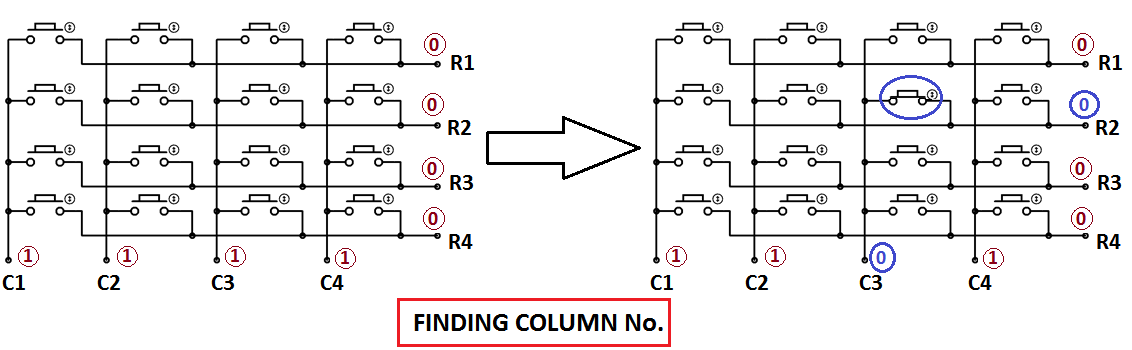
1. First, we have made all the Rows to Logic level 0 and all the columns to Logic level 1.
2. Whenever we press a button, the column and row corresponding to that button get shortened and the corresponding column logic level 0. Because that column becomes connected (shorted) to the row, which is at Logic level 0. So we get the column no. See main() function.
3. Now we need to find the Row no, so we have created four functions corresponding to each column. Like if any button of column one is pressed, we call the function row_finder1() to find the row no.
4. In row_finder1() function, we reversed the logic levels, which means now all the Rows are 1 and columns are 0. Now the Row of the pressed button should be 0 because it has become connected (shorted) to the column whose button is pressed, and all the columns are at 0 logic. So we have scanned all rows for 0.
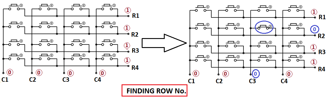
5. So whenever we find the Row at logic 0, it means that is the row of the pressed button. So now we have column no. (got in step 2) and row no., and we can print the number of that button using the lcd_data function.
Common Applications of 4x4 Keypad with 8051 Microcontroller
Understanding keypad interfacing with the 8051 microcontroller opens doors to numerous real-world applications:
| Application Domain | Use Cases | Key Benefits |
| Security Systems | Digital locks, access control panels, alarm systems | Password entry, user authentication |
| Consumer Electronics | Calculators, microwave ovens, washing machines | Numeric input, menu navigation |
| Telecommunications | Landline phones, intercom systems, PABX | Dial pad functionality, feature codes |
| Industrial Control | CNC machines, process controllers, HMI panels | Parameter input, command entry |
| Medical Devices | Patient monitors, diagnostic equipment, infusion pumps | Settings configuration, data entry |
| Automotive | Car security systems, GPS devices, dashboard controls | PIN entry, system configuration |
Technical Summary and GitHub Repository
Below is the complete 4x4 matrix keypad with 8051 microcontroller programming implementation in Embedded C. This code demonstrates professional-grade 8051 keypad interfacing with LCD display support. For developers working with 4x4 keypad interfacing with 8051 assembly code, here's a professional implementation using Assembly language programming:


The same procedure follows for every button press, and we are using a while(1), to continuously check whether the button is pressed or not.
Frequently Asked Questions on Keypad Interfacing with 8051 Microcontroller
⇥ Q1: Implementation of debouncing in keypad interfacing to the 8051 microcontroller.
Software debouncing is accomplished by waiting 20-50 ms after a keypress is detected before re-checking the pin status for the keypress to be valid. Hardware debouncing is accomplished easily with a 0.1µF capacitor in parallel with each switch. The code should be modified to support detecting a key release, again waiting for every column to go HIGH to accept the next keypress to prevent more than one character being detected by a single keypress.
⇥ Q2: Can multiple keypads interface with the 8051 microcontroller?
Yes, by connecting multiple keypads on different ports, or using multiplexing. Two 4x4 keypads will take 16 pins (Port 1 and Port 2). Or, you can use external multiplier ICs, such as 74HC138, to go through scan sequences with common data lines and select pins to perform a sequence scan for multiple keypads; ultimately allowing large expansion while keeping GPIO output to a minimum.
⇥ Q3: Scanning speed of a keypad while using the 8051 microcontroller?
Scanning speed is a function of crystal frequency and the time taken for loops to run. An 11.0592MHz crystal will take about 100-200 ms for a total scan of a 4x4 keypad. This corresponds to a scanning detection rate of 5,000-10,000 scans/second, to provide near-real-time keypress detection. A human is pressing a key, all of which take 50-100 ms, orders of magnitude longer, so detection modifications to the code are low frequency for error detection, extending multiple presses without an error.
⇥ Q4: Are pull-up resistors necessary for keypad interfacing?
Port 1 supports internal pull-ups (10-50kΩ), thus dispensing with the need for external resistors for columns. For Port 0 usage, provide external 10kΩ pull-up resistors on column pins since P0 does not support internal pull-ups. Pull-ups provide columns with logic HIGH when a key is not being pressed, establishing definite voltage levels for the stable scanning operation.
⇥ Q5: Detecting Simultaneous Key Presses for 4x4 Keypad
A single scanning input will only detect a single key being pressed. To detect multiple keys being pressed (N-key rollover), all the rows must be scanned all at once by retaining the full port state and moving the logic. Each port connected to the rows would then have to be examined amongst the port state bit patterns to detect multiple keys being pressed. Ghosting happens because of the way the matrix is arranged: a ghost key will be detected if all three corners of a rectangle are pressed. Diodes are needed for isolation and proper multi-key operation.
⇥ Q6: What is the maximum cable length for the 8051 to connect to the keypad?
Recommended maximum cable length for reliable operation is in the range of 30-50 cm, without additional circuitry. Cables longer than these dimensions would be 2-3 metres and would require using shielded cables, termination resistors, as well as noise filtering capacitors (0.1µF to ground). For truly industrial applications/beyond, cables over 3 meters should use an RS-485 interface or an I2C-based keypad controller for reliable signal transmission and to protect against noise.
⇥ Q7: How to be able to debug the keypad without the LCD?
Use LED indications on another port: assign 4 LEDs to represent the binary press sensed from 0-15. Another way to debug would be to send the key press via UART back to the PC terminal for serially displayed key press. If using an LCD (probably the most popular option), the display would also show the relevant digit displayed accurately as pressed. To assist development, simulation software such as Proteus with a virtual terminal will display on screen for each key press accurately in real time, all without needing a physical LCD connection.
Building Interactive Keypad Projects on PIC16F877A, ATmega32, and Arduino Nano
Dive into practical projects that showcase 4×4 matrix keypad interfacing across different microcontroller platforms. These projects provide hands-on insights into embedded system design, keypad handling, and creating engaging, interactive electronics projects across multiple platforms.

4x4 Matrix Keypad Interfacing with PIC Microcontroller
In this tutorial, we are going to interface a 4x4 matrix keypad with PIC16F877A. It will use 8 pins, out of which 4 are connected in rows and 4 connected in columns, therefore saving 8 pins of the microcontroller.

4x4 Keypad Interfacing with ATmega32 Microcontroller
In this tutorial, we are going to interface a 4x4 (16-key) keypad with an ATMEGA32A microcontroller. We know that a keypad is one of the most important input devices used in electronics projects.

Build a 4×4×4 LED Cube using Arduino Nano
In this project, we're making a cool 4×4×4 LED cube with Arduino Nano. LED cubes, also known as LED Matrix, can light up your room, study space, or Maker area, giving it an awesome, cool look. Moreover, it is very easy to build and helps you get creative with electronics and coding.
Complete Project Code
#include<reg51.h>
#define display_port P2      //Data pins connected to port 2 on microcontroller
sbit rs = P3^2;  //RS pin connected to pin 2 of port 3
sbit rw = P3^3;  // RW pin connected to pin 3 of port 3
sbit e =  P3^4;  //E pin connected to pin 4 of port 3
sbit C4 = P1^0;     // Connecting keypad to Port 1
sbit C3 = P1^1;
sbit C2 = P1^2;
sbit C1 = P1^3;
sbit R4 = P1^4;
sbit R3 = P1^5;
sbit R2 = P1^6;
sbit R1 = P1^7;
void msdelay(unsigned int time)  // Function for creating delay in milliseconds.
{
    unsigned i,j ;
    for(i=0;i<time;i++)
    for(j=0;j<1275;j++);
}
void lcd_cmd(unsigned char command)  //Function to send command instruction to LCD
{
    display_port = command;
    rs= 0;
    rw=0;
    e=1;
    msdelay(1);
    e=0;
}
void lcd_data(unsigned char disp_data)  //Function to send display data to LCD
{
    display_port = disp_data;
    rs= 1;
    rw=0;
    e=1;
    msdelay(1);
    e=0;
}
 void lcd_init()    //Function to prepare the LCD  and get it ready
{
    lcd_cmd(0x38);  // for using 2 lines and 5X7 matrix of LCD
    msdelay(10);
    lcd_cmd(0x0F);  // turn display ON, cursor blinking
    msdelay(10);
    lcd_cmd(0x01);  //clear screen
    msdelay(10);
    lcd_cmd(0x81);  // bring cursor to position 1 of line 1
    msdelay(10);
}
void row_finder1() //Function for finding the row for column 1
{
R1=R2=R3=R4=1;
C1=C2=C3=C4=0;
if(R1==0)
lcd_data('1');
if(R2==0)
lcd_data('4');
if(R3==0)
lcd_data('7');
if(R4==0)
lcd_data('*');
}
void row_finder2() //Function for finding the row for column 2
{
R1=R2=R3=R4=1;
C1=C2=C3=C4=0;
if(R1==0)
lcd_data('2');
if(R2==0)
lcd_data('5');
if(R3==0)
lcd_data('8');
if(R4==0)
lcd_data('0');
}
void row_finder3() //Function for finding the row for column 3
{
R1=R2=R3=R4=1;
C1=C2=C3=C4=0;
if(R1==0)
lcd_data('3');
if(R2==0)
lcd_data('6');
if(R3==0)
lcd_data('9');
if(R4==0)
lcd_data('#');
}
void row_finder4() //Function for finding the row for column 4
{
R1=R2=R3=R4=1;
C1=C2=C3=C4=0;
if(R1==0)
lcd_data('A');
if(R2==0)
lcd_data('B');
if(R3==0)
lcd_data('C');
if(R4==0)
lcd_data('D');
}
void main()
{
    lcd_init();
    while(1)
    {
        msdelay(30);
        C1=C2=C3=C4=1;
          R1=R2=R3=R4=0;
          if(C1==0)
          row_finder1();
          else if(C2==0)
           row_finder2();
           else if(C3==0)
        row_finder3();
        else if(C4==0)
        row_finder4();
    }
}
Comments
hi .
i;'m doing mini project by using 8051 with keypad at port 0, just wondering, when use Port 0, the keypad will hand and keep show 1111111 after i press 1 at keypad..if i use port 2, it is ok,,,i think, the program correct. it is something special in port 0
Have you changed the code accordingly? Also try increasing the delay in lcd_data.
Asalmualikum, port 0 of 8051 unlike other ports requires pull up resistors to output data
can i make the "*" key in the keypad to be used as a 'backspace' key ?
Shift the cursor before one character and type the new character, it will replace the old character.
thank you very much
Really it's a good plot from for learning embedded systems thanks you for doing great job and also please do more.
Thanks a lot!!!

Hi, just been reading through the code and I can't work out what language it's written in? Any help? Thanks