
Keypads are widely used input devices being used in various electronics and embedded projects. They are used to take inputs in the form of numbers and albhabets, and feed the same into system for further processing. In this tutorial we are going to interface a 4x4 matrix keypad with 8051 microcontroller.
4X4 Matrix Keypad
Before we interface the keypad with microcontroller, first we need to understand how it works. Matrix keypad consists of set of Push buttons, which are interconnected. Like in our case we are using 4X4 matrix keypad, in which there are 4 push buttons in each of four rows. And the terminals of the push buttons are connected according to diagram. In first row, one terminal of all the 4 push buttons are connected together and another terminal of 4 push buttons are representing each of 4 columns, same goes for each row. So we are getting 8 terminals to connect with a microcontroller.
Interfacing keypad with 8051 microcontroller (AT89S52)

First we need to interface a LCD module to display the data which will be feed through KEYPAD, so please go through “LCD Interfacing with 8051 Microcontroller” article before interfacing KEYPAD.
As shown in above circuit diagram, to interface Keypad, we need to connect 8 terminals of the keypad to any port (8 pins) of the microcontroller. Like we have connected keypad terminals to Port 1 of 8051. Whenever any button is pressed we need to get the location of the button, means the corresponding ROW an COLUMN no. Once we get the location of the button, we can print the character accordingly.
Now the question is how to get the location of the pressed button? I am going to explain this in below steps and also want you to look at the code:
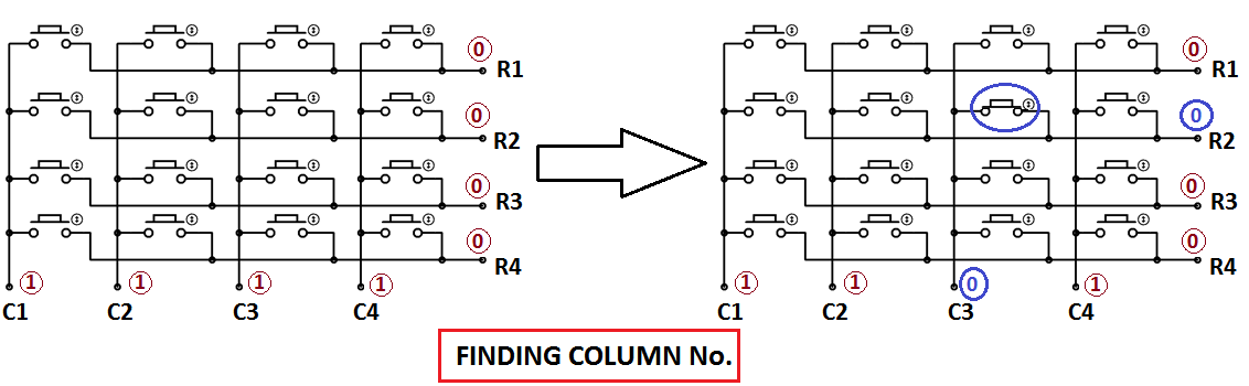
1. First we have made all the Rows to Logic level 0 and all the columns to Logic level 1.
2. Whenever we press a button, column and row corresponding to that button gets shorted and makes the corresponding column to logic level 0. Because that column becomes connected (shorted) to the row, which is at Logic level 0. So we get the column no. See main() function.
3. Now we need to find the Row no., so we have created four functions corresponding to each column. Like if any button of column one is pressed, we call function row_finder1(), to find the row no.
4. In row_finder1() function, we reversed the logic levels, means now all the Rows are 1 and columns are 0. Now Row of the pressed button should be 0 because it has become connected (shorted) to the column whose button is pressed, and all the columns are at 0 logic. So we have scanned all rows for 0.
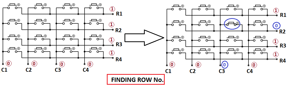
5. So whenever we find the Row at logic 0, means that is the row of pressed button. So now we have column no (got in step 2) and row no., and we can print no. of that button using lcd_data function.
Same procedure follows for every button press, and we are using while(1), to continuously check, whether button is pressed or not.
Complete Project Code
#include<reg51.h>
#define display_port P2      //Data pins connected to port 2 on microcontroller
sbit rs = P3^2;  //RS pin connected to pin 2 of port 3
sbit rw = P3^3;  // RW pin connected to pin 3 of port 3
sbit e =  P3^4;  //E pin connected to pin 4 of port 3
sbit C4 = P1^0;     // Connecting keypad to Port 1
sbit C3 = P1^1;
sbit C2 = P1^2;
sbit C1 = P1^3;
sbit R4 = P1^4;
sbit R3 = P1^5;
sbit R2 = P1^6;
sbit R1 = P1^7;
void msdelay(unsigned int time)  // Function for creating delay in milliseconds.
{
    unsigned i,j ;
    for(i=0;i<time;i++)
    for(j=0;j<1275;j++);
}
void lcd_cmd(unsigned char command)  //Function to send command instruction to LCD
{
    display_port = command;
    rs= 0;
    rw=0;
    e=1;
    msdelay(1);
    e=0;
}
void lcd_data(unsigned char disp_data)  //Function to send display data to LCD
{
    display_port = disp_data;
    rs= 1;
    rw=0;
    e=1;
    msdelay(1);
    e=0;
}
 void lcd_init()    //Function to prepare the LCD  and get it ready
{
    lcd_cmd(0x38);  // for using 2 lines and 5X7 matrix of LCD
    msdelay(10);
    lcd_cmd(0x0F);  // turn display ON, cursor blinking
    msdelay(10);
    lcd_cmd(0x01);  //clear screen
    msdelay(10);
    lcd_cmd(0x81);  // bring cursor to position 1 of line 1
    msdelay(10);
}
void row_finder1() //Function for finding the row for column 1
{
R1=R2=R3=R4=1;
C1=C2=C3=C4=0;
if(R1==0)
lcd_data('1');
if(R2==0)
lcd_data('4');
if(R3==0)
lcd_data('7');
if(R4==0)
lcd_data('*');
}
void row_finder2() //Function for finding the row for column 2
{
R1=R2=R3=R4=1;
C1=C2=C3=C4=0;
if(R1==0)
lcd_data('2');
if(R2==0)
lcd_data('5');
if(R3==0)
lcd_data('8');
if(R4==0)
lcd_data('0');
}
void row_finder3() //Function for finding the row for column 3
{
R1=R2=R3=R4=1;
C1=C2=C3=C4=0;
if(R1==0)
lcd_data('3');
if(R2==0)
lcd_data('6');
if(R3==0)
lcd_data('9');
if(R4==0)
lcd_data('#');
}
void row_finder4() //Function for finding the row for column 4
{
R1=R2=R3=R4=1;
C1=C2=C3=C4=0;
if(R1==0)
lcd_data('A');
if(R2==0)
lcd_data('B');
if(R3==0)
lcd_data('C');
if(R4==0)
lcd_data('D');
}
void main()
{
    lcd_init();
    while(1)
    {
        msdelay(30);
        C1=C2=C3=C4=1;
          R1=R2=R3=R4=0;
          if(C1==0)
          row_finder1();
          else if(C2==0)
           row_finder2();
           else if(C3==0)
        row_finder3();
        else if(C4==0)
        row_finder4();
    }
}
Comments
hi .
i;'m doing mini project by using 8051 with keypad at port 0, just wondering, when use Port 0, the keypad will hand and keep show 1111111 after i press 1 at keypad..if i use port 2, it is ok,,,i think, the program correct. it is something special in port 0
Have you changed the code accordingly? Also try increasing the delay in lcd_data.
Asalmualikum, port 0 of 8051 unlike other ports requires pull up resistors to output data
can i make the "*" key in the keypad to be used as a 'backspace' key ?
Shift the cursor before one character and type the new character, it will replace the old character.
thank you very much
Really it's a good plot from for learning embedded systems thanks you for doing great job and also please do more.
Thanks a lot!!!

Hi, just been reading through the code and I can't work out what language it's written in? Any help? Thanks