

Few years back if you were to tell someone that the Geyser and bedroom lights in your home are connected to internet, they would be baffled and might even criticize it as over-engineered products. But today with the advent of IoT, Smart cities etc the idea no longer sounds strange, we have devices around us that have become smarter by being able to communicate with the internet.
In this project our aim is to leverage this IoT into the boring attendance system to make it smart and more effective. Most conventional attendance systems available today store the information over a micro SD card and have to be connected to software via a computer to access the information. Here, we will build a biometric attendance system using Arduino that scans for finger print and on successful identification of the person it will log the information to a cloud platform like ThingsBoard by using the ESP8266 Wi-Fi module. This information can then be displayed in the dashboard of ThingsBoard making it available for the required authorities to view and analysis information over the internet without having any direct physical access to the hardware. However the conventional Attendance system without involving IoT can also be built by following the link and Finger print sensor can be further used for many other biometric applications like Voting Machine, Security system etc.
Hardware Required
- Arduino UNO
- 16x2 LCD Display
- Arduino WiFi Shield
- ESP8266-01
- GT511C3 Finger print sensor (FPS)
- 12V Adapter
Pre-requisites
We will be writing two Arduino scripts for this program. One for the ESP8266-01 Module and the other is for Arduino UNO. The reason is that Arduino was not able to handle both GT511C3 sensor and ESP8266 through AT commands via software serial. Hence we will write two codes, one for Arduino in which it will communicate with the FPS and send the obtained values via software serial to ESP8266. The other code will be written for ESP8266 which will enable the module to be connected to the Thingsboard server and then will receive the values from Arduino through serial communication to update them on Thingsboard Dashboard.
If you have built the Wi-Fi Shield from our previous tutorial of Arduino WiFi Shield, then this project can be build under 30 minutes. If not, try building it since the Gerber file, and circuit was provided already in that tutorial. Even if you don’t have one, do not worry for we will be covering the circuit again in this tutorial as well. It is also advised to go through GT511C3 Finger Print Sensor with Arduino tutorial before you proceed with this to understand how to enroll and detect finger prints using the GT511C3 module.
Preparing your Thingsboard account
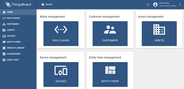
There are many open source cloud platforms available today for your IoT project integrations. Each platform has its own specialty, for our application I was looking for something that is good in data logging and visualization and found Thingsboard.io to suit that purpose. So let’s start by setting up the Thingsboard account first. Get into thingboard.io and click on “TRY IT NOW” and then under the community edition (because it’s free) click on Live Demo. You will be taken to a sign-up page, it is a simple procedure in which you have to link and confirm your Email ID and once done you will be taken to the home page which will look something like this. If you are stuck you can refer to this getting started Thingsboard video.
On ThingsBoard we have two important terms, Assets and Devices. You can think of assets as buildings, warehouses, industry, farmland etc and devices as the sensor or devices present in that particular asset. So every asset will have one or more devices in it based on the project, here we will have one asset and one device in our asset.
Creating an Asset on Thingsboard
Let’s start by creating our first asset, click on assets on your left panel and you will notice all the assets related to your account, you might have none or some example assets which you can ignore. To create an asset click on the add icon on the bottom right corner of the screen which creates a pop-up promoting for Name, Asset type and Description. You can give any name and type, I have given the following
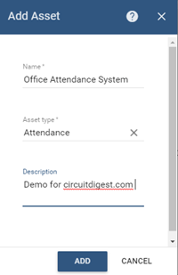
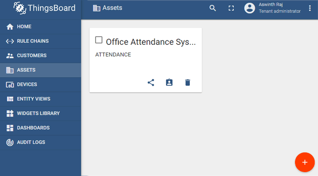
Once the details are entered just click on Add and your asset will be created. Note that I have named by asset as , remember this for we will need it later. Once the asset is created you can notice it appearing on the window as shown below.
Adding a Device to the Asset
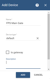
Now that we have created an asset we should add a device to it. To do so click on the device tab on the left panel and then click on add icon on the bottom right corner of the screen. You will get a similar pop up in which you to name the device I have name mine as FPS main gate and device type as default.
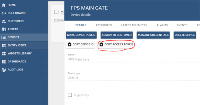
Click on add and then you will find the device being created on the panel, click on the device that we just created and you will notice a new panel sliding in from the right. This panel will have all the information about the device, just click on copy access token as shown below to get the token value of our device, we will need this value in our Arduino program to send or receive values to this device.
Creating Device Relation for Asset
After creating your asset and device, go back to your asset tab and click on the asset that we just created. My asset is named as “Office Attendance System”. This will slide in a pop-up from the right, now select relations tab in the new pop-up and over outbound relations click on add (+) symbol to get the following pop-up
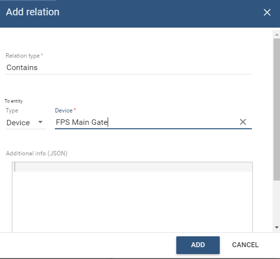
Select entity type as Device and enter the name of the device that we created earlier. My device name was “FPS Main Gate” which I have entered above. Finally click on Add button to add the device relationship to asset.
Preparing the ESP8266-01
The ESP8266 should be operated both in AT command mode and Programming mode for this project. We can use a LM317 to regulate 3.3V for powering the ESP8266 module and connect the Tx Rx pins to FTDI board as shown below.
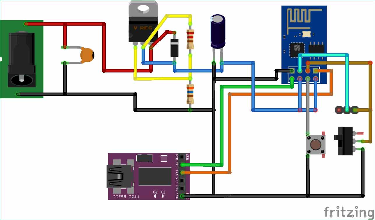
The toggle switch can be used to toggle the ESP8266 between AT command mode and Programming mode and push button can be pressed to reset the module. Note that the ESP8266 has to be reset every time before a code is being uploaded to it. If you are confused on how to do it you can refer to the basics of ESP8266, including how to use ESP8266 in AT command mode and Flash firmware on it.
This circuit will only be used to upload the program to ESP8266, later we will replace the FTDI board with Arduino UNO in our final set-up.
Programming ESP8266 with Arduino IDE for sending data to ThingsBoard
We have to program the ESP8266 to connect to our Wi-Fi router and sync in with our ThingsBoard device using the token address that we obtained earlier. Once that is done it should actively look for details coming from the Arduino board through its serial pins and if it gets a data it should phrase the information and send it to the Thingsboard dashboard. The complete program to do that same can be found at the bottom of this page. The explanation for the same is as follows. Before proceeding with the program makes sure you have already installed the required board details in your Arduino IDE using board manager to program ESP8266 with Arduino also install the following libraries using Sketch -> Include Library -> Manage Library. Just search for the required library and click on install.
Once the IDE is ready we can begin the program by adding the required libraries and providing the Wifi credential and password with the Token value that we obtained earlier. Then create a Wi-Fi client that connects to the Thingsboard demo page. The code for the same is shown below.
#include <PubSubClient.h> //pubsubclient.knolleary.net/
#include <ESP8266WiFi.h> //https://github.com/bportaluri/WiFiEsp
#define WIFI_AP "CircuitLoop"
#define WIFI_PASSWORD "pasword14785"
#define TOKEN "IFhm5ggJVsEpokiIoQ"
char thingsboardServer[] = "demo.thingsboard.io";
WiFiClient wifiClient;
Important: Make sure you change the TOKEN and Wi-Fi credentials according to your device.
Inside the setup function we will begin the serial communication at 9600 baud rate and initialize the Wi-Fi module to connect to the Wi-Fi router. Finally we will connect our Wi-Fi client to the ThingsBoard server.
void setup()
{
  Serial.begin(9600);
  delay(10);
  InitWiFi();
  client.setServer( thingsboardServer, 1883 );
  lastSend = 0;
}
Inside the loop function we will constantly check if the connection to server is active, if not we will try a reconnection using the reconnect function. If the client connection is successful the program will check for incoming data from the Serial monitor, if data is received it will converted to string and stored in the variable called Name. This variable will then be sent to the ThingsBoard server in json format using the function Send_to_Thingsboard(). If there is no serial data coming in then we will just maintain the client connection by using the line client.loop().
void loop()
{
  if ( !client.connected() ) {
    reconnect();
  }
  if ( Serial.available() ) { // Update and send only after 1 seconds
    char a = Serial.read();
    Name = Name + String(a);
    if (a == 13) //check for new line
    {
    Name.trim(); //Remove /n or /r from the incomind data
    Serial.println(Name);
    Send_to_Thingsboard();
    Name =""; //clear the string if new line is detected
    }
  }
  client.loop();
}
Thingsboard server accepts information in form of JSON, so we have to construct our payload from ESP8266 in JSON format. We can do that by simply using string cascading function in Arduino. We also name our payload as “Name”. The attributes has to mention the size of the payload that we are sending to Thingsboard. Since the number of characters in each employee name will vary our payload will not have a fixed attribute value so we set it to a maximum of 100. Then to send them over ESP8266 we have to convert the String to char using the toCharArray method and finally send it using the client.publish option. Note the v1/devices/me/telemetry should not be changed.
void Send_to_Thingsboard()
{
  Serial.println("Collecting temperature data.");
  String Employee_Name = Name;
  // Prepare a JSON payload string
  String payload = "{";
  payload += "\"Name\":"; payload += Employee_Name;
  payload += "}";
  // Send payload
  char attributes[100];
  payload.toCharArray( attributes, 100 );
  client.publish( "v1/devices/me/telemetry", attributes );
  Serial.println( attributes );
}
Testing ESP8266 connection with ThingsBoard
Once your IDE and hardware is ready, we can check if the ESP8266 Part is working well. Using the FTDI module in the above discussed circuit upload the code to ESP8266 by keeping it in programming mode. Once the code is uploaded connect it back to AT command mode and press the reset button. Then open serial monitor and you should see the following
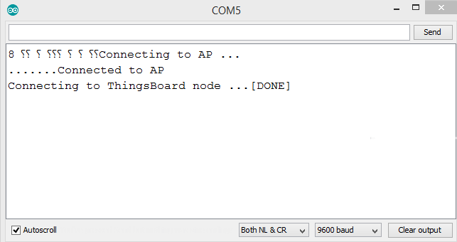
This message confirms that the ESP8266 module was able to establish communication with our device on Thingsboard server. At this stage the ESP is waiting for input through its Serial monitor, when it receives something it will send that data to the server. So, now it’s time to connect the ESP with Arduino to provide the values to ESP.
Circuit diagram for IoT based Attendance System
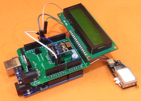
For the final circuit, we will port the existing circuit and replace the FTDI module with Arduino UNO with the GT511C3 FPS and LCD screen connected to it. The final circuit diagram is shown below.

This time make sure you put your ESP8266 in AT command mode and not in Programming mode. The complete project can be powered by a 12V adapter directly through the Vin pin of the Arduino UNO. The 16x2 LCD is connected to display the name of the person who has been identified.
Another important thing to notice is that the metal casing of the FPS is connected to pin 10 of Arduino. This is to turn off the FPS when not in use. As we know the FPS needs a blue LED to be turned on to take optical images of fingerprints and recognize them. But if this light is always kept on the sensor tends to get hot which might reduce its life. Luckily I found a method mentioned in its datasheet to overcome this problem, which is to use the metal casing of the sensor as a touch sensor. When a person have to use the FPS he has to touch the metal frame, so if we can sense his body capacitance we will be able to say if a person has touched the FPS or not.
Programming Arduino UNO for Biometric Attendance System
The Program on Arduino is pretty simple, as we know from our previous interfacing tutorial when a fingerprint is enrolled a template is created and a ID is allocated to the person. So all we have to do it look for the ID and relate it to a name and send this name to ESP826 through serial communication. This name will then be sent to the ThingsBoard device. Additionally I have also enabled an option to enroll finger print through Admin, that is if the admin presses his finger then Arduino will prompt you to enroll a new finger print. The complete program for all these is given in the bottom of this page, the explanation of code is as follows.
The first step is to relate the ID number with employee name. I have used a string array for 5 employees including Admin. Hence the person with ID number 0 will be Admin and 1 will be Steve and so on. Thus for five employees ID number from 0 to 4 will be used. If the admin enroll a new finger print of a new employee he will have id number 5 which can be related to his name.
char *Name_List[]= {"Admin", "Steve", "Tony", "Natasha", "Bruce"};
If you have not noticed yet, then yes the admin here is Nick Furry (wink). Moving on, we can start our program by adding all the required libraries. You would have to install the following two additional libraries to your Arduino IDE
The GT511C3 library can be used to enroll, detect fingerprints with the FPS through Arduino. The Capacitive touch sensor library allows us to check if someone has touched the metal casing on the FPS. Once the libraries are added to Arduino include them in the program as shown below
#include "FPS_GT511C3.h" //Get library from https://github.com/sparkfun/Fingerprint_Scanner-TTL
#include "SoftwareSerial.h" //Software serial library
#include <LiquidCrystal.h> //Library for LCD
#include "OnePinCapSense.h" //Librarey to sensor capacitive touch https://github.com/MrYsLab/OnePinCapSense
We have connected the Rx and Tx pins of ESP with pin 12 and 13 and the FPS sensor serial pins to pin 9 and 8. So we can create two separate serial software instance for both as shown below. Also we have mentioned that pin 10 is to be used a capacitive touch sensor and LCD is connected to pins D2 to D7.
Softwareserial ESP(12, 13); // RX, TX
FPS_GT511C3 fps(9, 8); //FPS connected to D9 and D8
const int rs = 7, en = 6, d4 = 5, d5 = 4, d6 = 3, d7 = 2; //Mention the pin number for LCD connection
LiquidCrystal lcd(rs, en, d4, d5, d6, d7);//Initialize LCD method
int capSensePin10  = 10; //Pin to which casing of sensor is connected
Inside the setup function we initialize the Serial communication at 9600 baud rate and display a small intro message on the LCD. We have also opened communication with FPS and have turned its blue LED off if it has been left on earlier.
void setup()
{
  Serial.begin(9600);
  ESP.begin (9600);
  lcd.begin(16, 2); //Initialise 16*2 LCD
  lcd.print("GT511C3 FPS"); //Intro Message line 1
  lcd.setCursor(0, 1);
  lcd.print("with Arduino"); //Intro Message line 2
  delay(2000);
  lcd.clear();
  fps.Open();         //send serial command to initialize fps
  fps.SetLED(false);   //turn on LED so fps can see fingerprint
}
Inside the loop function we have to check if someone is touching the sensor to begin any work. This can be check by reading the capacitive pin using readCapacitivePin option. For our set-up I found that the read value exceeds 50 all times when the casing is not touched and goes below 50 when someone touches it. So we can use to it check if the sensor is being touched. If the sensor is touched we just have to turn on the blue LED.
int capSense10 = opcs.readCapacitivePin(capSensePin10) ;
 if( capSense10 < 50)
 { fps.SetLED(true); delay(500);}
Once the blue LED is turned on the sensor will be able to detect if the object touching it is a finger or not. If it is a finger then we capture the image of the fingerprint and identify it to obtain its ID number. If the ID number is 200 it means that the identified finger print has not been enrolled yet. So we will display unknown, if the ID is 0 then it means the identified fingerprint is of the admin so we proceed with enrolling a new finger print. If the identified number is within our name list then we can proceed with displaying their name on LCD and also sending the information to ESP. After the process we can finally turn off the blue LED until a new finger touch is detected.
  if (fps.IsPressFinger())
  {
    fps.CaptureFinger(false);
    id = fps.Identify1_N();
      lcd.clear();
      if (id==200)
      {
      lcd.print("Unkown"); lcd.setCursor(0,1); lcd.print("Try Again!!");//If not recognised
      }
      else if (id==0)
      {
       lcd.print("Welcome"); lcd.setCursor(0,1); lcd.print("***ADMIN***");//If not recognised
       delay(2000);
       Enroll();
      }
      else
      {
        lcd.print("Thank You"); lcd.setCursor(0,1); lcd.print(Name_List[id]); ESP.println(Name_List[id]);
        Serial.println("Sent Value to ESP");
      }
      delay(1000);
      fps.SetLED(false);
  }
Testing the complete IoT based Arduino Attendance System
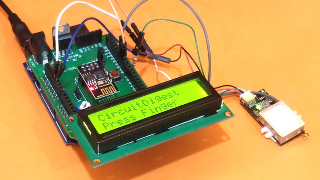
Finally it’s time to get the system into action, upload the Arduino code to the UNO board and connect it with ESP which already has our code running using the circuit diagram given above. Power up the module and if everything goes good you should notice the LCd display saying “Press Finger” as shown below.
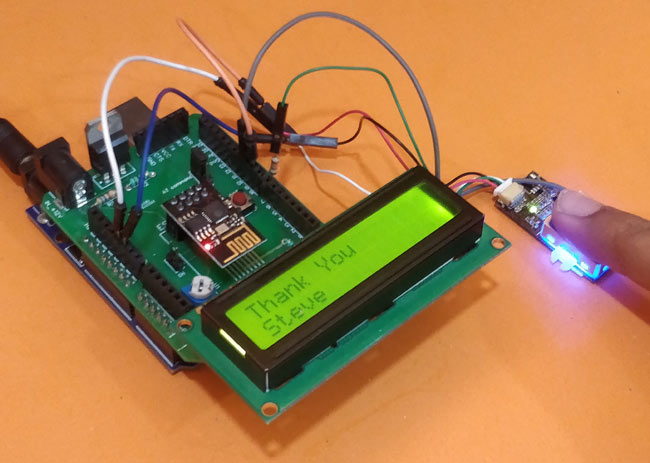
Now make sure that the fingerprints are enrolled in the FPS by following the previous tutorial and then touch the sensor with a enrolled finger. If detected the LCD will say Thank you followed by the name of that person and will also send the name of the person to ESP which will then send to the thingsboard device that we created earlier.
Checking if ThingsBoard is receiving the Attendance Data
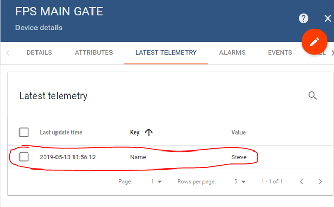
In previous step our FPS sensor detected Steve and hence the same name has been sent to thingsboard as you can see here. If you do not get anything here, make sure your ESP is connected and powered properly and is able to get information from Arduino though serial and send it to client.
Creating a Dashboard on ThingsBoard for IoT Attendance System
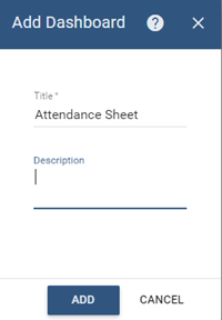
The final step is to create a dashboard in which we can view all the names sent by the ESP module against time and date. The good thing with ThingsBoard is that you have many widgets to visualize the data based on usage. It is also possible to use the rule chain option to logically analyze these data and take required actions like triggering an alarm sending E-mail etc. To create a dashboard click on dashboard in the left panel, then click on add new dashboard (+) icon on the bottom left of the screen. And select create new dashboard. In the pop-up give a name to your dashboard and click on add.
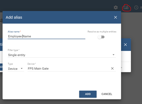
This will create a new dashboard on the dashboards window. Click on this new dashboard and enter edit mode by clicking on the pencil icon (orange color) on the bottom right corner of the screen. Now we have to create an alias by clicking on the create alias icon (encircled red in below image) and add a new alias name by clicking on add button. In pop-up window enter the name of your choice and select type as device and mention the name of the device from which we need the data on the dashboard as shown below and click on add and then save button.
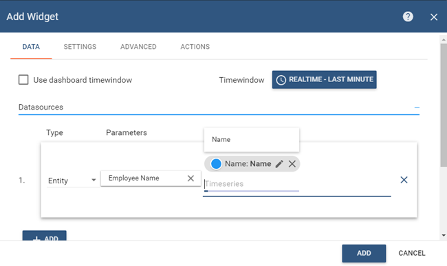
Click on add new widget and then under the current bundle select cards and then select time series table. This will open a window and ask for the alias name that we just created, you can select the type as entity and provide the alias name as shown in the below picture.
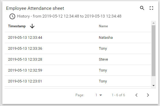
Click on add and you should see a new widget on your dashboard with the name of all the employees that have been sent by the ESP so far. You can also sort the data name vise or use the history option to view the data in a particular date or time. My sample dataset is shown below
You can also view the data in real time and as you press the finger on the FPS the name of the Employee should appear on this window. That is it we created a Smart IoT based attendance system that updates all data on our dashboard which can be visualized, analyzed and reported online without the need of physical contact with the hardware. Once the project is ready hand it over to Nick Furry and ask him assemble the Avengers on time, the next time when someone decides to wipe out half the population.
The complete working of the project can also be found in the video given below. Hope you understood the project and enjoyed building something useful. If you have any questions regarding this project leave them in the comment section below or use our forums for other technical queries.
Complete Project Code
Code for Arduino
/*
* Arduino with GT511C2 FingerPrint Sensor (FPS)
* Code to enroll and Detect Fingers
* For: www.circuitdigest.com
* Dated: 6-5-19
* Code By: Aswinth
*
* Connect Tx of FPS to Arduino Pin D4 and Rx of FPS to D5
*/
char *Name_List[]= {"ADMIN", "Mahesh", "Aswinth", "Munna", "Pankaj", "Sandeep", "Ashok", "Gust 1", "Gust 2", "Gust 3", "Gust 4"};
#include "FPS_GT511C3.h" //Get library from https://github.com/sparkfun/Fingerprint_Scanner-TTL
#include "SoftwareSerial.h" //Software serial library
#include <LiquidCrystal.h> //Library for LCD
#include "OnePinCapSense.h" //Librarey to sensor capacitive touch https://github.com/MrYsLab/OnePinCapSense
SoftwareSerial ESP(12, 13); // RX, TX
FPS_GT511C3 fps(9, 8); //FPS connected to D9 and D8
const int rs = 7, en = 6, d4 = 5, d5 = 4, d6 = 3, d7 = 2; //Mention the pin number for LCD connection
LiquidCrystal lcd(rs, en, d4, d5, d6, d7);//Initialize LCD method
int capSensePin10 = 10; //Pin to which casing of sensor is connected
int id = 200;
OnePinCapSense opcs = OnePinCapSense();
void setup()
{
Serial.begin(9600);
ESP.begin (9600);
lcd.begin(16, 2); //Initialise 16*2 LCD
lcd.print("GT511C3 FPS"); //Intro Message line 1
lcd.setCursor(0, 1);
lcd.print("with Arduino"); //Intro Message line 2
delay(2000);
lcd.clear();
fps.Open(); //send serial command to initialize fps
fps.SetLED(false); //turn on LED so fps can see fingerprint
}
void loop()
{
int capSense10 = opcs.readCapacitivePin(capSensePin10) ;
if( capSense10 < 100)
{ fps.SetLED(true); delay(500);}
Serial.println(capSense10);
// Identify fingerprint test
if (fps.IsPressFinger())
{
fps.CaptureFinger(false);
id = fps.Identify1_N();
lcd.clear();
if (id==200)
{
lcd.print("Unkown"); lcd.setCursor(0,1); lcd.print("Try Again!!");//If not recognised
}
else if (id==0)
{
lcd.print("Welcome"); lcd.setCursor(0,1); lcd.print("***ADMIN***");//If not recognised
delay(2000);
Enroll();
}
else
{
lcd.print("Thank You"); lcd.setCursor(0,1); lcd.print(Name_List[id]); ESP.println(Name_List[id]);
Serial.println("Sent Value to ESP");
}
delay(1000);
fps.SetLED(false);
}
else
{
fps.SetLED(false);
lcd.clear();
lcd.print("CircuitDigest"); //Display intro text
lcd.setCursor(0,1);
lcd.print("Press Finger");
}
}
void Enroll() //Enrol function from library exmaple program
{
int enrollid = 0;
bool usedid = true;
while (usedid == true)
{
usedid = fps.CheckEnrolled(enrollid);
if (usedid==true) enrollid++;
}
fps.EnrollStart(enrollid);
// enroll
lcd.clear();
lcd.print("Enroll #");
lcd.print(enrollid);
while(fps.IsPressFinger() == false) delay(100);
bool bret = fps.CaptureFinger(true);
int iret = 0;
if (bret != false)
{
lcd.clear();
lcd.print("Remove finger");
fps.Enroll1();
while(fps.IsPressFinger() == true) delay(100);
lcd.clear(); lcd.print("Press again");
while(fps.IsPressFinger() == false) delay(100);
bret = fps.CaptureFinger(true);
if (bret != false)
{
lcd.clear(); lcd.print("Remove finger");
fps.Enroll2();
while(fps.IsPressFinger() == true) delay(100);
lcd.clear(); lcd.print("Press yet again");
while(fps.IsPressFinger() == false) delay(100);
bret = fps.CaptureFinger(true);
if (bret != false)
{
lcd.clear(); lcd.print("Remove finger");
iret = fps.Enroll3();
if (iret == 0)
{
lcd.clear(); lcd.print("Enrolling Success");
}
else
{
lcd.clear();
lcd.print("Enroll Failed:");
lcd.print(iret);
}
}
else lcd.print("Failed 1");
}
else lcd.print("Failed 2");
}
else lcd.print("Failed 3");
}
Code for ESP8266
/*Program to connect ESP8266 to thingsboard and sent the value received through serial input
* For IoT Attendance Project
* Author: B.Aswinth Raj
* Dated: 11-5-2019
* Website: www.circuitdigest.com
*/
#include <PubSubClient.h> //pubsubclient.knolleary.net/
#include <ESP8266WiFi.h> //https://github.com/bportaluri/WiFiEsp
#define WIFI_AP "CircuitLoop"
#define WIFI_PASSWORD "circuitdigest101"
#define TOKEN "lrmsUz2M4cA9wN3dVmUX"
char thingsboardServer[] = "demo.thingsboard.io";
WiFiClient wifiClient;
PubSubClient client(wifiClient);
int status = WL_IDLE_STATUS;
unsigned long lastSend;
void setup()
{
Serial.begin(9600);
delay(10);
InitWiFi();
client.setServer( thingsboardServer, 1883 );
lastSend = 0;
}
String Name ="";
void loop()
{
if ( !client.connected() ) {
reconnect();
}
if ( Serial.available() ) { // Update and send only after 1 seconds
char a = Serial.read();
Name = Name + String(a);
if (a == 13) //check for new line
{
Name.trim(); //Remove /n or /r from the incomind data
Serial.println(Name);
Send_to_Thingsboard();
Name =""; //clear the string if new line is detected
}
}
client.loop();
}
void Send_to_Thingsboard()
{
Serial.println("Collecting temperature data.");
String Employee_Name = Name;
// Prepare a JSON payload string
String payload = "{";
payload += "\"Name\":"; payload += Employee_Name;
payload += "}";
// Send payload
char attributes[100];
payload.toCharArray( attributes, 100 );
client.publish( "v1/devices/me/telemetry", attributes );
Serial.println( attributes );
}
void InitWiFi()
{
Serial.println("Connecting to AP ...");
// attempt to connect to WiFi network
WiFi.begin(WIFI_AP, WIFI_PASSWORD);
while (WiFi.status() != WL_CONNECTED) {
delay(500);
Serial.print(".");
}
Serial.println("Connected to AP");
}
void reconnect() {
// Loop until we're reconnected
while (!client.connected()) {
status = WiFi.status();
if ( status != WL_CONNECTED) {
WiFi.begin(WIFI_AP, WIFI_PASSWORD);
while (WiFi.status() != WL_CONNECTED) {
delay(500);
Serial.print(".");
}
Serial.println("Connected to AP");
}
Serial.print("Connecting to ThingsBoard node ...");
// Attempt to connect (clientId, username, password)
if ( client.connect("ESP8266 Device", TOKEN, NULL) ) {
Serial.println( "[DONE]" );
} else {
Serial.print( "[FAILED] [ rc = " );
Serial.print( client.state() );
Serial.println( " : retrying in 5 seconds]" );
// Wait 5 seconds before retrying
delay( 5000 );
}
}
}
Comments
Hi Birat,
The capacitor used here is 0.1uF cermaic capacitor. The values of resistors is given in the circuit diagram itself. It can be identified by reading the colour code on the resistor
Hello Sir.
I'm doing the similar project like this one and I'm quite confused with the circuit diagram. Is it possible for you to give a brief explaination of the circuit diagram and also explain the different components and its value used in the voltalge divider?
I would be really grateful if you could help me out. Thanking you in advance.
Hello Sir,
I have a question according to this project. can I use built-in Arduino Wifi Shield (https://store.arduino.cc/usa/arduino-wifi-shield) as a replacement?
I am one Question

Heloo sir! It would be a great help if you mention the values of electronics components used i.e capacitors, transistors etc..Thanks in advance :-D