

Input devices play a vital role in any electronics projects. These input device help the user to interact with the digital world. An input device can be as simple as a push button or as complicated as a touch screen; it varies based on the requirement of the project. In this tutorial we are going to learn how to interface a joystick with our PIC microcontroller, a joystick is a cool way to interact with the digital world and almost everyone would have used one for playing video games in their adolescence age.
A joystick might seem to be a sophisticated device, but it actually is just a combination of two Potentiometers and a push button. Hence it is also very easy to interface with any MCU provided we know how to use the ADC feature of that MCU. We have already learnt how to use ADC with PIC , hence it is would be just a work around for interfacing the Joystick. For people who are new to pickit is recommended to learn the above ADC project as well as the LED Blinking Sequence Project to make it easier to understand the project.
Material Required
- PicKit 3 for programming
- Joy Stick module
- PIC16F877A IC
- 40 - Pin IC holder
- Perf board
- 20 MHz Crystal OSC
- Bergstik pins
- 220ohm Resistor
- 5-LEDs of any colour
- 1 Soldering kit
- IC 7805
- 12V Adapter
- Connecting wires
- Breadboard
Understanding the Joystick Module:
Joysticks are available in different shapes and sizes. A typical Joystick module is shown in the figure below. A Joystick is nothing more than a couple of potentiometers and push button mounted over a smart mechanical arrangement. The potentiometer is used to keep track of the X and Y movement of the joystick and the button is used to sense if the joystick is pressed. Both the Potentiometers output an analog voltage which depends on the position of the joystick. And we can get the direction of movement by interpreting these voltage changes using some microcontroller. Previously we interfaced Joystick with AVR, Joystick with Arduino and Raspberry Pi.
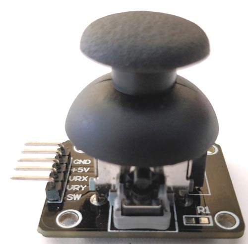
Before interfacing any sensor or module with a microcontroller it is important to know how it functions. Here our joystick has 5 output pins out of which two is for power and three is for data. The module should be powered with +5V. The data pins are named as VRX, VRY and SW.
The term “VRX” stands for Variable voltage on X-axis and the term “VRY” stands for Variable voltage in Y-axis and “SW” stands for switch.
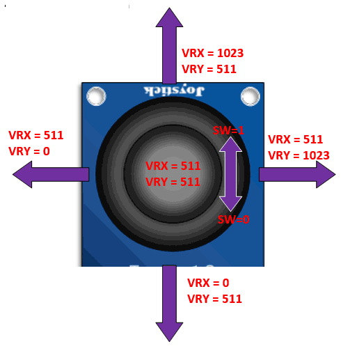
So when we move the joystick to left or right the voltage value on VRX will vary and when we vary it up or down VRY will vary. Similarly when we move it diagonally we both VRX and VRY will vary. When we press the switch the SW pin will be connected to ground. The below figure will help you to understand the Output values much better
Circuit Diagram:
Now that we know how the Joy stick works, we can arrive at a conclusion that we will need two ADC pins and one digital input pin to read all the three data pins of the Joystick module. The complete circuit diagram is shown in the picture below

As you can see in circuit diagram, instead of the joystick we have used two potentiometer RV1 and RV3 as analog voltage inputs and a logic input for the switch. You could follow the labels written in violet colour to match the pins names and make your connections accordingly.
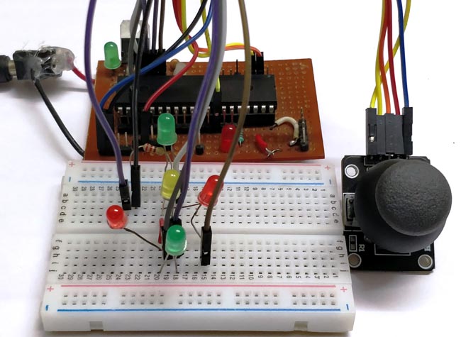
Note that the Analog pins are connected to channels A0 and A1 and the digital switch is connected to RB0. We will also have 5 LED lights connected as output, so that we can glow one based on the direction the joystick is moved. So these output pins are connected to PORT C from RC0 to RC4. Once we have panned our circuit diagram we can proceed with the programming, then simulate the program on this circuit then build the circuit on a breadboard and then upload the program to the hardware. To give you an idea my hardware after making the above connections is shown below
Programming for Interfacing the Joystick:
The program to interface joystick with PIC is simple and straight forward. We already know that which pins the Joystick is connected to and what their function is, so we simply have to read the analog voltage from the pins and control the output LED’s accordingly.
The complete program to do this is given at the end of this document, but for explaining things I am breaking the code in to small meaningful snippets below.
As always the program is started by setting the configuration bits, we are not going to discuss much about setting configurations bits because we have already learnt it in the LED Blinking project and it is the same for this project also. Once the configurations bits are set we have to define the ADC functions for using the ADC module in our PIC. These function were also learnt in the how to use ADC with PIC tutorial. After that, we have to declare which pins are inputs and which are output pins. Here the LED is connected to PORTC so they are output pins and the Switch pin of Joystick is a digital input pin. So we use the following lines to declare the same:
//*****I/O Configuration****//
TRISC=0X00; //PORT C is used as output ports
PORTC=0X00; //MAke all pins low
TRISB0=1; //RB0 is used as input
//***End of I/O configuration**///
The ADC pins need not be defined as input pins because they when using the ADC function it will be assigned as input pin. Once the pins are defined, we can call the ADC_initialize function which we defined earlier. This function will set the required ADC registers and prepare the ADC module.
ADC_Initialize(); //Configure the ADC module
Now, we step into our infinite while loop. Inside this loop we have to monitor the values of VRX, VRY and SW and based on the values we have to control the led’s output. We can begin the monitoring process by reading the analog voltage of VRX and VRY by using the below lines
    int joy_X = (ADC_Read(0)); //Read the X-Axis of joystick
    int joy_Y = (ADC_Read(1)); //Read the Y-Axis of Joystick
This line will save the value of VRX and VRY in the variable joy_X and joy_Y respectively. The function ADC_Read(0) means we are reading the ADC value from channel 0 which is pin A0. We have connected VRX and VRY to pin A0 and A1 and so we read from 0 and 1.
If you can recollect from our ADC tutorial we know that we read the Analog Voltage the PIC being a digital device will read it from 0 to 1023. This value depends on the position of the joystick module. You can use the label diagram above to know what value you can expect for every position of the joystick.
Here I have used the limit value of 200 as lower limit and a value of 800 as upper limit. You can use anything you want. So let’s use these values and start glowing the LED s accordingly. To do this we have to compare the value of joy_X with the pre-defined values using an IF loop and make the LED pins high or low as shown below. The comment lines will help you to understand better
    if (joy_X < 200) //Joy moved up
    {RC0=0; RC1=1;} //Glow upper LED
    else if (joy_X > 800) //Joy moved down
    {RC0=1; RC1=0;} //Glow Lower LED
    else //If not moved
    {RC0=0; RC1=0;} //Turn off both led
We can similarly do the same for the value of Y-axis as well. We just have to replace the variable joy_X with joy_Y and also control the next two LED pins as shown below. Note that when the joystick is not moved we turn off both the LED lights.
    if (joy_Y < 200) //Joy moved Left
    {RC2=0; RC3=1;} //Glow left LED
    else if (joy_Y > 800) //Joy moved Right
    {RC2=1; RC3=0;} //Glow Right LED
    else //If not moved
    {RC2=0; RC3=0;} //Turn off both LED
Now we have one more final thing to do, we have to check the switch if is pressed. The switch pin is connected to RB0 so we can again use if loop and check if it is on. If it is pressed we will turn of the LED to indicate that the switch has been pressed.
    if (RB0==1) //If Joy is pressed
        RC4=1; //Glow middle LED
    else
        RC4=0; //OFF middle LED
Simulation View:
The complete project can be simulated using the Proteus software. Once you have written the program compile the code and link the hex code of the simulation to the circuit. Then you should notice the LED lights glowing according to the position of the potentiometers. The simulation is shown below:

Hardware and Working:
After verifying the code using the Simulation, we can build the circuit on a bread board. If you have been following the PIC tutorials you would have noticed that we use the same perf board which has the PIC and 7805 circuit soldered to it. If you are also interested in making one so that you use it with all your PIC projects then solder the circuit on a perf board. Or you can also build the complete circuit on a breadboard also. Once the hardware is done it would be something like this below.
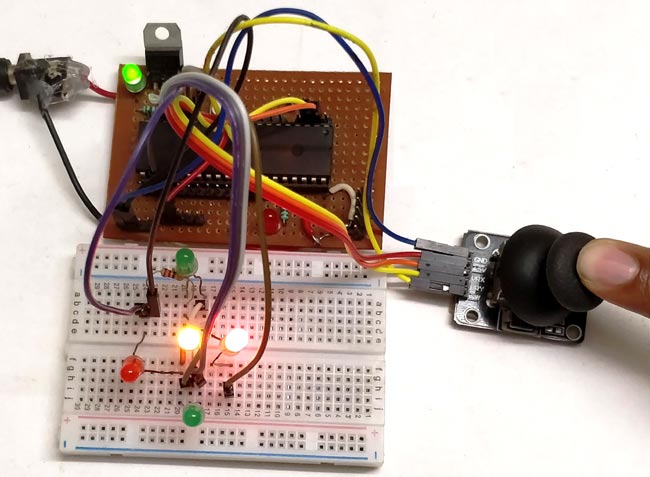
Now upload the code to the PIC microcontroller using the PICkit3. You can refer the LED Blink project for guidance. You should notice the yellow light go high as soon as the program is uploaded. Now use the joystick and vary the knob, for each direction of the joystick you will notice the respective LED going high. When the switch in the middle is pressed, it will turn off the LED in the middle.
This working is just an example, you can build a lot of interesting projects on top it. The complete working of the project can also be found at the video given at the end of this page.
Hope you understood the project and enjoyed building it, if you have any problem in doing so feel free to post it on the comment section below or write it on the forums for getting help.
Complete Project Code
/*

 * File:   PIC_Joystick.c

 * Author: Aswinth

 * This program can read the values from a joy stick and control the LED based on the values

 * Created on 3 May, 2018, 4:05 PM for www.circuitdigest.com

 */
// CONFIG

#pragma config FOSC = HS        // Oscillator Selection bits (HS oscillator)

#pragma config WDTE = OFF       // Watchdog Timer Enable bit (WDT disabled)

#pragma config PWRTE = ON       // Power-up Timer Enable bit (PWRT enabled)

#pragma config BOREN = ON       // Brown-out Reset Enable bit (BOR enabled)

#pragma config LVP = OFF        // Low-Voltage (Single-Supply) In-Circuit Serial Programming Enable bit (RB3 is digital I/O, HV on MCLR must be used for programming)

#pragma config CPD = OFF        // Data EEPROM Memory Code Protection bit (Data EEPROM code protection off)

#pragma config WRT = OFF        // Flash Program Memory Write Enable bits (Write protection off; all program memory may be written to by EECON control)

#pragma config CP = OFF         // Flash Program Memory Code Protection bit (Code protection off)
// #pragma config statements should precede project file includes.

// Use project enums instead of #define for ON and OFF.
#include <xc.h>

#define _XTAL_FREQ 20000000
void ADC_Initialize()

{

  ADCON0 = 0b01000001; //ADC ON and Fosc/16 is selected

  ADCON1 = 0b11000000; // Internal reference voltage is selected

}
unsigned int ADC_Read(unsigned char channel)

{

  ADCON0 &= 0x11000101; //Clearing the Channel Selection Bits

  ADCON0 |= channel<<3; //Setting the required Bits

  __delay_ms(2); //Acquisition time to charge hold capacitor

  GO_nDONE = 1; //Initializes A/D Conversion

  while(GO_nDONE); //Wait for A/D Conversion to complete

  return ((ADRESH<<8)+ADRESL); //Returns Result

}
void main()

{

//*****I/O Configuration****//

TRISC=0X00; //PORT C is used as output ports

PORTC=0X00; //MAke all pins low

TRISB0=1; //RB0 is used as input

//***End of I/O configuration**///
ADC_Initialize(); //Configure the ADC module

while(1)

{
    int joy_X = (ADC_Read(0)); //Read the X-Axis of joystick

    int joy_Y = (ADC_Read(1)); //Read the Y-Axis of Joystick


    if (joy_X < 200) //Joy moved up

    {RC0=0; RC1=1;} //Glow upper LED

    else if (joy_X > 800) //Joy moved down

    {RC0=1; RC1=0;} //Glow Lower LED

    else //If not moved

    {RC0=0; RC1=0;} //Turn off both led


    if (joy_Y < 200) //Joy moved Left

    {RC2=0; RC3=1;} //Glow left LED

    else if (joy_Y > 800) //Joy moved Right

    {RC2=1; RC3=0;} //Glow Right LED

    else //If not moved

    {RC2=0; RC3=0;} //Turn off both LED


    if (RB0==1) //If Joy is pressed

        RC4=1; //Glow middle LED

    else

        RC4=0; //OFF middle LED


}

}
Comments
Will this work for controlling a RC Tank? Or should one use a controller allready made for RC's? Then just right the code using a Adruino?

I want to know about hybrid inverter with solar charging battery