 with STM32F10C8 Blue Pill Board")
We all know that the Microcontrollers work only with digital values but in real world we have to deal with analog signals. That’s why ADC (Analog to Digital Converters) is there to convert real world Analog values into Digital form so that microcontrollers can process the signals. But what if we need Analog signals from digital values, so here comes the DAC (Digital to Analog Converter).
A simple example for Digital to Analog converter is recording a song in studio where an artist singer is using microphone and singing a song. These analog sound waves are converted into digital form and then stored in a digital format file and when the song is played using the stored digital file those digital values are converted into analog signals for speaker output. So in this system DAC is used.
DAC can be used in many applications such as Motor control, Control Brightness of the LED Lights, Audio Amplifier, Video Encoders, Data Acquisition Systems etc.
We already interfaced MCP4725 DAC Module with Arduino. Today we will use the same MCP4725 DAC IC to design a Digital to Analog converter using the STM32F103C8 Microcontroller.
Components Required
- STM32F103C8
- MCP4725 DAC IC
- 10k Potentiometer
- 16x2 LCD display
- Breadboard
- Connecting Wires
MCP4725 DAC Module (Digital to Analog Converter)
MCP4725 IC is a 12-Bit Digital to Analog Converter Module which is used to generate output analog voltages from (0 to 5V) and it is controlled by using I2C communication. It also comes with on board nonvolatile memory EEPROM.
This IC has 12-Bit resolution. This means we use (0 to 4096) as input to provide the voltage output with respect to reference voltage. Maximum reference voltage is 5V.
Formula to calculate Output Voltage
O/P Voltage = (Reference Voltage / Resolution) x Digital Value
For Example if we use 5V as reference voltage and let’s assume that digital value is 2048. So to calculate the DAC output.
O/P Voltage = (5/ 4096) x 2048 = 2.5V
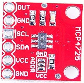
Below is the image of MCP4725 with clearly indicating pin names.
|
Pins of MCP4725 |
Use |
|
OUT |
Outputs Analog Voltage |
|
GND |
GND for Output |
|
SCL |
I2C Serial Clock line |
|
SDA |
I2C Serial Data line |
|
VCC |
Input Reference Voltage 5V or 3.3V |
|
GND |
GND for input |
I2C Communication in MCP4725
This DAC IC can be interfaced with any microcontroller using the I2C communication. I2C communication requires only two wires SCL and SDA. By default, the I2C address for MCP4725 is 0x60. Follow the link to know more about I2C communication in STM32F103C8.
I2C pins in STM32F103C8:
SDA: PB7 or PB9, PB11.
SCL: PB6 or PB8, PB10.

Circuit Diagram and Explanation

Connections between STM32F103C8 & 16x2 LCD
|
LCD Pin No |
LCD Pin Name |
STM32 Pin Name |
|
1 |
Ground (Gnd) |
Ground (G) |
|
2 |
VCC |
5V |
|
3 |
VEE |
Pin from Centre of Potentiometer for contrast |
|
4 |
Register Select (RS) |
PB11 |
|
5 |
Read/Write (RW) |
Ground (G) |
|
6 |
Enable (EN) |
PB10 |
|
7 |
Data Bit 0 (DB0) |
No Connection (NC) |
|
8 |
Data Bit 1 (DB1) |
No Connection (NC) |
|
9 |
Data Bit 2 (DB2) |
No Connection (NC) |
|
10 |
Data Bit 3 (DB3) |
No Connection (NC) |
|
11 |
Data Bit 4 (DB4) |
PB0 |
|
12 |
Data Bit 5 (DB5) |
PB1 |
|
13 |
Data Bit 6 (DB6) |
PC13 |
|
14 |
Data Bit 7 (DB7) |
PC14 |
|
15 |
LED Positive |
5V |
|
16 |
LED Negative |
Ground (G) |
Connection between MCP4725 DAC IC and STM32F103C8
|
MCP4725 |
STM32F103C8 |
Multimeter |
|
SDA |
PB7 |
NC |
|
SCL |
PB6 |
NC |
|
OUT |
PA1 |
Positive Probe |
|
GND |
GND |
Negative Probe |
|
VCC |
3.3V |
NC |
A potentiometer is also connected, with center pin connected to PA1 analog input (ADC) of STM32F10C8, Left Pin connected to GND and right most pin connected to 3.3V of STM32F103C8.
In this tutorial we will connect a MCP4725 DAC IC with STM32 and use a 10k potentiometer to provide analog input value to STM32 ADC pin PA0. And then use ADC to convert analog value into digital form. After that send those digital values to MCP4725 via I2C bus. Then convert those digital values to analog using the DAC MCP4725 IC and then use another ADC pin PA1 of STM32 to check the analog output of MCP4725 from the pin OUT. Finally display the both ADC & DAC values with voltages in the 16x2 LCD display.
Programming STM32F103C8 for Digital to Analog Conversion
A FTDI programmer is not needed now to upload code to STM32F103C8. Simply connect it to PC via USB port of STM32 and start programming with ARDUINO IDE. Visit this link to learn more about Programming your STM32 in Arduino IDE. Complete program for this STM32 DAC tutorial is given at the end.
First include library for I2C and LCD using wire.h , SoftWire.h and liquidcrystal.h library. Learn more about I2C in STM32 Microcontroller here.
#include<Wire.h>
#include <LiquidCrystal.h>
#include<SoftWire.h>
Next define and initialize the LCD pins according to the LCD pins connected with the STM32F103C8
const int rs = PB11, en = PB10, d4 = PB0, d5 = PB1, d6 = PC13, d7 = PC14;
LiquidCrystal lcd(rs, en, d4, d5, d6, d7);
Then define the I2C address of the MCP4725 DAC IC. The MCP4725 DAC default I2C address is 0x60
#define MCP4725 0x60
In the void setup()
First begin the I2C communication at the pins PB7 (SDA) and PB6 (SCL) of STM32F103C8.
Wire.begin(); //Begins the I2C communication
Next set the LCD display in the 16x2 mode and display a welcome message.
  lcd.begin(16,2);
  lcd.print("CIRCUIT DIGEST");
  delay(1000);
  lcd.clear();
  lcd.setCursor(0,0);
  lcd.print("STM32F103C8");
  lcd.setCursor(0,1);
  lcd.print("DAC with MCP4725");
  delay(2000);
  lcd.clear();
In the void loop()
1. First in buffer[0] put the control byte value (0b01000000).
(010-Sets MCP4725 in Write mode)
buffer[0] = 0b01000000;
2. Following statement reads the analog value from pin PA0 and converts it into digital value ranging from 0 to4096 as ADC is 12-bit resolution and store in the variable adc.
adc = analogRead(PA0) ;
3. This following statement is a formula used to calculate the voltage from the ADC input value (0 to 4096) with the reference voltage of 3.3V.
float ipvolt = (3.3/4096.0)* adc;
4. Put the Most significant bit values in buffer[1] by shifting 4 bits to right in ADC variable, and Least significant bit values in buffer[2] by shifting 4 bits to left in adc variable.
buffer[1] = adc >> 4;
buffer[2] = adc << 4;
5. The following statement reads analog value from ADC pin PA1 of STM32 that is the DAC output (MCP4725 DAC IC’s OUTPUT pin). This pin can also be connected to multimeter to check the output voltage.
unsigned int analogread = analogRead(PA1);
6. Further the voltage value from the variable analogread is calculated using the formula with the following statement.
float opvolt = (3.3/4096.0)* analogread;
7. In the same void loop () there are few other statements which are explained below
Begins the transmission with MCP4725:
Wire.beginTransmission(MCP4725);
Sends the control byte to I2C
Wire.write(buffer[0]);
Sends the MSB to I2C
Wire.write(buffer[1]);
Sends the LSB to I2C
Wire.write(buffer[2]);
Ends the transmission
Wire.endTransmission();
Now display those results in the LCD 16x2 display using lcd.print()
  lcd.setCursor(0,0);
  lcd.print("A IP:");
  lcd.print(adc);
  lcd.setCursor(10,0);
  lcd.print("V:");
  lcd.print(ipvolt);
  lcd.setCursor(0,1);
  lcd.print("D OP:");
  lcd.print(analogread);
  lcd.setCursor(10,1);
  lcd.print("V:");
  lcd.print(opvolt);
  delay(500);
  lcd.clear();
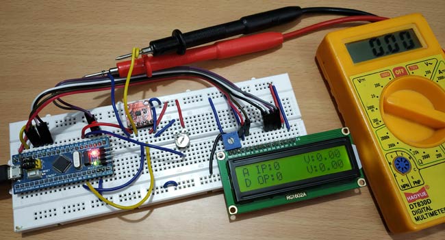
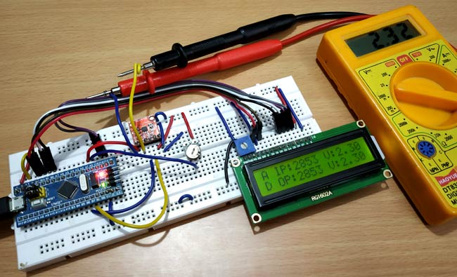
Testing the DAC with STM32
When we vary the input ADC value and voltage by rotating the potentiometer, the output DAC value and voltage also changes. Here the input values are shown in the first row and output values in second row of LCD display. A multimeter is also connected to the MCP4725 Output Pin to verify the analog voltage.
Complete code with demonstration Video is given below.
Complete Project Code
#include<Wire.h>                   //Include Wire library for using I2C functions

#include<SoftWire.h>

#include <LiquidCrystal.h>         //Include LCD library for using LCD display functions
#define MCP4725 0x60            //MCP4725 address as 0x60 Change yours accordingly
const int rs = PB11, en = PB10, d4 = PB0, d5 = PB1, d6 = PC13, d7 = PC14;

LiquidCrystal lcd(rs, en, d4, d5, d6, d7);
unsigned int adc;

byte buffer[3];
void setup()

{

  Wire.begin();                    //Begins the I2C communication

  lcd.begin(16,2);                 //Sets LCD in 16X2 Mode

  lcd.print("CIRCUIT DIGEST");

  delay(1000);

  lcd.clear();

  lcd.setCursor(0,0);

  lcd.print("STM32F103C8");

  lcd.setCursor(0,1);

  lcd.print("DAC with MCP4725");

  delay(2000);

  lcd.clear();

}
void loop()
{

  buffer[0] = 0b01000000;            //Sets the buffer0 with control byte (010-Sets in Write mode)

  adc = analogRead(PA0);             //Read Analog value from pin PA0


  float ipvolt = (3.3/4096.0)* adc;  //Finding voltage formula

  buffer[1] = adc >> 4;              //Puts the most significant bit values

  buffer[2] = adc << 4;              //Puts the Least significant bit values


  unsigned int analogread = analogRead(PA1) ; //Reads analog value from PA1


  float opvolt = (3.3/4096.0)* analogread; //Finding Voltage Formula


  Wire.beginTransmission(MCP4725);         //Joins I2C bus with MCP4725 with 0x60 address


  Wire.write(buffer[0]);            //Sends the control byte to I2C

  Wire.write(buffer[1]);            //Sends the MSB to I2C

  Wire.write(buffer[2]);            //Sends the LSB to I2C


  Wire.endTransmission();           //Ends the transmission
  lcd.setCursor(0,0);

  lcd.print("A IP:");

  lcd.print(adc);                   //Prints the ADC value from PA0

  lcd.setCursor(10,0);

  lcd.print("V:");                  //Prints the Input Voltage at PA0

  lcd.print(ipvolt);

  lcd.setCursor(0,1);

  lcd.print("D OP:");

  lcd.print(analogread);             //Prints the ADC value from PA1 (From DAC)

  lcd.setCursor(10,1);

  lcd.print("V:");

  lcd.print(opvolt);                 //Prints the Input Voltage at PA1 (From DAC)


  delay(500);

  lcd.clear();

}

Hi, while doing a digital simulation in Proteus I could not get the numeric values in the LCD screen which were to be read and displayed. I have also attached an image of the circuit during simulation to show, can you please share where am I going wrong.