

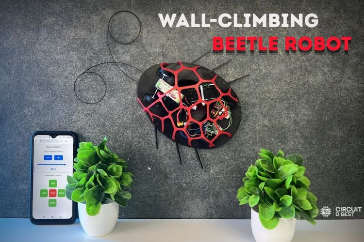
We can see wall-climbing robots from hobby-level to serious problem-solving ones that are used for inspection, surveillance, cleaning, etc. When we generally talk about robots, a robot can be a firefighting robot, a human-following robot, a self-balancing robot or can be of any type that has some specific features or solves a specific kind of problem. If we talk about wall-climbing robots, they rely on large drone motors, 5” propellers and bulky lipo batteries to generate enough holding power for climbing vertical surfaces.
In this ESP32 wall climbing robot project, we challenge ourselves to build a much smaller version. The goal is to create a lightweight wall-climbing robot that is small enough to fit in the palm of your hand while still generating sufficient suction to climb walls and crawl across ceilings. Instead of keeping it looking like another robot, we are going to design it to resemble a real beetle using a custom lightweight 3D-printed shell. If you're wondering how to make a simple wall climbing robot at home using an ESP32, this build walks through the full process, from suction theory to code.
Table of Contents
- What is a Wall Climbing Robot?
- └ Key Advantages
- Components
- How Does the Wall Climbing Robot Suction Work?
- Measuring the Holding Force
- Circuit Diagram
- 3D Model Design
- Designing the Beetle Top Shell
- 3D Printing
- Assembly
- Web Application for Controlling
- Code Explanation
- Final Result
- Troubleshooting
- GitHub
What is a Wall Climbing Robot?
The robot that climbs walls is a type of robot that can attach itself and move around on vertical or inverted surfaces like walls or ceilings. One of the methods that this type of robot uses to ensure that it is able to stick to the surface is through vacuum pumps, magnetic adhesion (in case of iron surfaces), or through spinning propellers that create a zone of low pressure on the underside of the robot. The industrial versions of robots of this type are used for carrying out inspections, for cleaning tanks, or for reconnaissance missions in inaccessible places for humans. This project attempts to build a robot of that type that would be the size of a small beetle and would be controlled with the help of an ESP32 microcontroller.
Key Advantages of This ESP32 Wall Climbing Robot
Understanding the advantages of this ESP32 wall climbing robot compared to typical designs can help to realise why it is worth building:
- Lightweight and compact: It weighs about 102 grams, allowing it to fit in a hand without being as cumbersome as production devices.
- No glue and dry residues used: This robot cannot damage walls and ceilings since it uses air rather than any sticky substances.
- Only a single motor needed: It produces more than 360 g of gripping force with only 1 BLDC engine working, saving on both energy and complexity.
- Benefit from wireless connection: It can be controlled via its own ESP32 web server using a browser from a mobile phone.
- Low price: The device can be built from widely available parts, making it affordable for amateurs.
- Accessible repair: All components can be easily downloaded.
Components Used for Making a Wall Climbing Robot
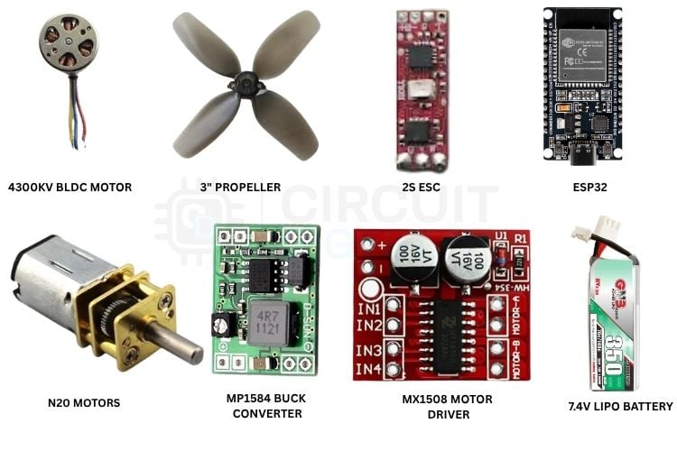
Below is the complete list of components used for making this wall climbing robot, along with what each part does in the overall system.
| S.no | Component | Description | Quantity |
| 1 | 4300KV Brushless DC Motor | To provide the suction / holding power to the robot | 1 |
| 2 | 3-inch Drone Propeller | Acts as the main propeller | 1 |
| 3 | ESP32 Development Board | Main controller | 1 |
| 4 | 100 RPM N20 Motors | To provide movement for the robot | 2 |
| 5 | Lightweight Wheels | Wheels with rubber grips give better traction | 4 |
| 6 | 2S, 6-8A ESC | Drive the BLDC Motor | 1 |
| 7 | 7.4V 350mAh Li-Po Battery | Power the whole robot | 1 |
| 8 | MX1508 Motor Driver | Drive the N20 Motors | 1 |
| 9 | MP1584 Buck converter | Provide stable 5V to ESP32 | 1 |
How Does the Wall Climbing Robot Suction Work?
Instead of using some adhesive pads or vacuum pumps, this robot uses a high-speed BLDC motor and propeller to generate a low-pressure region beneath the chassis.
As the propeller spins, it continuously pulls air from underneath the robot and throws it upwards. This creates a pressure difference between the inside of the enclosure and the surrounding atmosphere. The higher atmospheric pressure outside pushes the robot firmly against the wall or ceiling, creating the holding force required for climbing. The stronger the pressure difference, the greater the holding force.
Measuring the Holding Force
The entire assembly was placed on a weighing machine. The weighing machine that I use shows positive values when weight is on top of it and negative values when we pull the plate up. After weighing all the electronic components, including the battery, ESP32 board, BLDC motor, ESC, and drive motors, the total weight came to approximately 137 grams.
For reliable climbing, the suction force should be significantly higher than the robot's own weight. A safe and optimal holding force is around two times the total weight. Therefore, our target holding force is at least 274 grams. After trials and optimizing the design, we got a suction force of 360 grams.
Circuit Diagram of the ESP32 Wall Climbing Robot
Below is the circuit diagram for the Wall Climbing Beetle robot.

The brain of the robot is an ESP32 development module. The NZO motors are connected to the output pins of the MX1508 motor driver. The 4 inputs of the motor driver are connected to GPIOs 16,17,18 and 19 of the ESP32, respectively. The motor ESC is connected to the output pins of the 2S ESC, which is connected to GPIO pin 4. If you like to see more ESP32-based projects, check out our collection of ESP32 projects.
The buck converter, which is MP1584, is connected directly to the 7.4V 350mAh LiPo battery. The 5V output is used to power the ESP32 as well as the motor driver. The 2S ESC is also connected directly to the battery so that we get the full potential of the battery.
3D Model Design of the Beetle Robot
Let’s take a detailed look at the 3D CAD model of the Beetle Robot. Below are the top and bottom views of the robot.
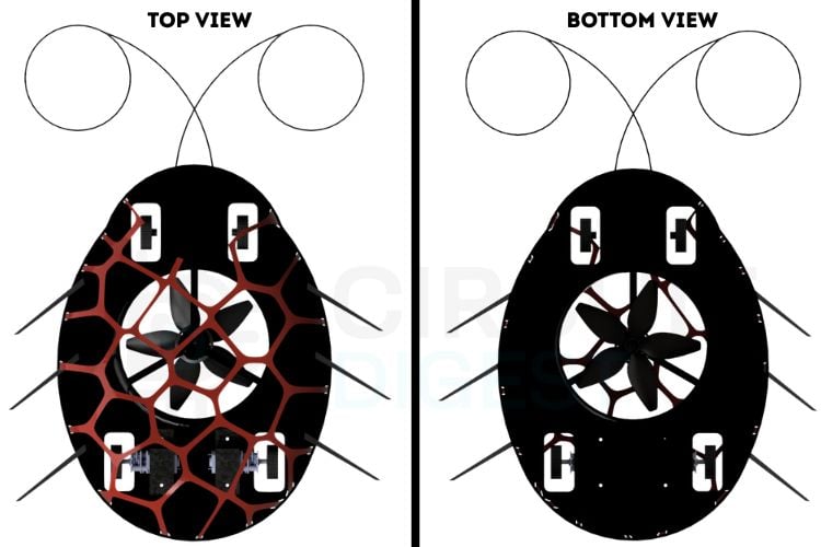
The bottom part, or chassis, in which all the components are mounted, is of 0.5mm thickness. Initially, the wheels were reused from an old toy car, but still, to reduce the weight, they were 3D printed with 0.5mm thickness, and we reused the rubber grips for better traction on walls and ceilings. A normal 2mm rod was cut and used as the axle with the front wheels. The back wheels were mounted directly to the motor shafts. The beetle horns and legs are glued to the main body. The horns do look like two separate ones, but to make things easier, they are designed as a single part so that they are stronger together.
The beetle top is of 0.4mm thickness. To properly mount the top and bottom, we have added slots in the bottom part that match the individual stripes of the beetle top. Simply connect the individual stripes to the respective slots and apply some glue; both parts are joined. The STL files can be downloaded and 3D printed as per one’s need.
Designing the Beetle Top Shell
Now, let’s have a look at the various steps involved in designing the Beetle’s top portion.
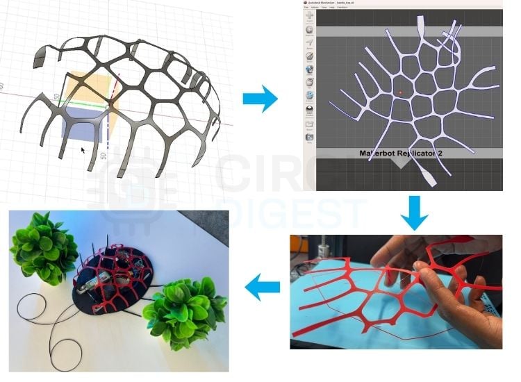
The coolest and most interesting part of this whole project is the design of the Beetle top. This involved a fair amount of design skills, mechanical knowledge and some creativity. In engineering, a lot of advancements are inspired by nature. For our beetle also, we planned to mimic some real beetle patterns. But for sure there will be a gap between design and reality. We looked for various designs and patterns that are seen in a real-life beetle, made hand sketches, and got suggestions from ChatGPT. We picked the honeycomb-like pattern that was given by ChatGPT and converted it into a Voronoi pattern. The whole design process is shown in the simple diagram below. Initially, we had a 3D Model in Autodesk Fusion. We converted it to a Surface model design and then imported it to Autodesk Meshmixer, where we flattened the design. We again imported the flattened design to Fusion, fixed the overlapping issues that happened when flattening the design, resized it to match the actual size and then 3D printed. After 3D printing the design, we mounted it to the beetle’s bottom part and glued the joints together.
3D Printing the Beetle Body
Below are the steps from start to end involved in designing, fabrication and modelling of the Beetle body.
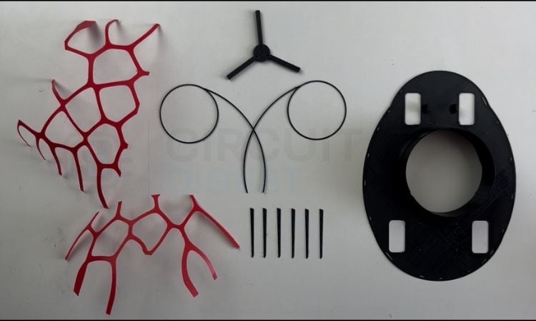
Printing the curved pattern is a bit complicated as it’s only 0.5mm thick and requires a lot of supports to hold the curves. Also, the chances are high that we are going to break the design trying to remove the supports. After the first 3D print failed, I planned to flatten the design for printing and, after the print is done, reshape it into the actual design by heating it. The flattened top design was large enough that it didn’t fit the print bed. So, the design was sliced into two halves. As seen in the image above, the red beetle top was two halves. Then they were glued together. The rest of the parts were printed in black colour. The files can be downloaded from the link below and printed with the colours of your choice.
Assembly of the Wall Climbing Robot
Below are the robot assembly details for reference.
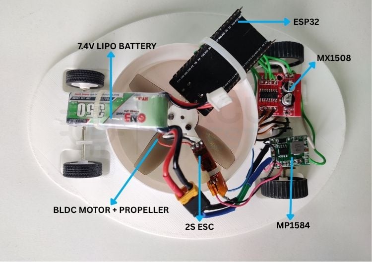
As you can see, the above is the full assembly of the Beetle. At the heart is the BLDC motor with propeller. The ESP32 and the Battery were moved to the center as much as possible to reduce tripping torque. The buck converter and the motor driver are mounted on top of the N20 motor mounting clamps. The jumper wires from the previous version were replaced with normal wires and were organized properly. After properly assembling all the parts, the robot closely resembled a beetle while remaining lightweight enough for wall-climbing. The completed robot successfully climbed vertical walls, crawled across ceilings, and demonstrated how careful optimization of weight distribution, structural design and airflow adjustment can produce an effective miniature wall-climbing beetle robot.
Web Application for Controlling the Robot
Below is a detailed description of the mobile web app that we use to control the beetle.
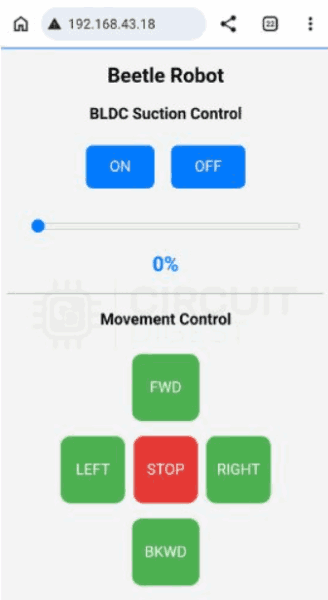
After the code is flashed into the ESP32 board using Arduino IDE, the serial monitor displays the IP Address of the ESP32. Enter it in your browser, and you’ll be taken to the following Web page. It has a really simple interface. starts with the BLDC motor control. Then you have the controls for the N20 motors as well. For Forward, both the motors spin in the CCW direction; for Backwards, both spin in the CW direction; for Left, the left motor spins in CCW and the right motor in the CW direction and vice versa for Right. For Stop, both motors stop spinning. There are several other similar kinds of IoT based projects that we have made. All of them are listed on our website as IoT projects.
ESP32 Wall Climbing Robot Code Explanation
Below is the detailed code explanation for this project.
#include <WiFi.h>
#include <WebServer.h>
const char* ssid = "wifi_name";
const char* password = "wifi_password7";
WebServer server(80);
// ESC
const int escPin = 4;
const int pwmFreq = 50;
const int pwmResolution = 16;
// MX1508
const int L1 = 16;
const int L2 = 17;
const int R1 = 18;
const int R2 = 19;
bool bldcEnabled = false;
int throttle = 0;
uint32_t usToDuty(uint16_t us)
{
uint32_t maxDuty = (1UL << pwmResolution) - 1;
return (uint32_t)((us / 20000.0) * maxDuty);
}
Libraries initialized, WiFi and GPIO pins configured for the BLDC motor and the N20 Motors.
This function “uint32_t usToDuty” converts the pulse width (in microseconds) into the corresponding PWM duty cycle required by the ESC.
void setThrottle(int percent)
{
 if (!bldcEnabled)
 {
   ledcWrite(escPin, usToDuty(1000));
   return;
 }
 percent = constrain(percent, 0, 100);
 uint16_t pulse =
     map(percent, 0, 100, 1000, 2000);
 ledcWrite(escPin, usToDuty(pulse));
}
This function controls the BLDC motor speed from 0 to 100%
void stopRobot()
{
 digitalWrite(L1, LOW);
 digitalWrite(L2, LOW);
 digitalWrite(R1, LOW);
 digitalWrite(R2, LOW);
}
void forward()
{
 digitalWrite(L1, HIGH);
 digitalWrite(L2, LOW);
 digitalWrite(R1, HIGH);
 digitalWrite(R2, LOW);
}
void backward()
{
 digitalWrite(L1, LOW);
 digitalWrite(L2, HIGH);
 digitalWrite(R1, LOW);
 digitalWrite(R2, HIGH);
}
void left()
{
 digitalWrite(L1, LOW);
 digitalWrite(L2, HIGH);
 digitalWrite(R1, HIGH);
 digitalWrite(R2, LOW);
}
void right()
{
 digitalWrite(L1, HIGH);
 digitalWrite(L2, LOW);
 digitalWrite(R1, LOW);
 digitalWrite(R2, HIGH);
}
The above functions are responsible for stopping the robot, moving forward, backwards, left and right. It functions by turning the corresponding GPIO pins High/Low.
void handleRoot()
{
}
This function generates the HTML web page that contains the clickable buttons for controlling the Beetle Robot.
void handleSpeed()
{
throttle =
  server.arg("value").toInt();
setThrottle(throttle);
server.send(200, "text/plain", "OK");
}
void handleBLDCOn()
{
bldcEnabled = true;
setThrottle(throttle);
server.send(200, "text/plain", "ON");
}
This function executes whenever the browser sends a request to /speed, and the speed value is extracted, converted into an integer and passed to setThrottle() to update the ESC throttle.
When the ON button is pressed, the variable “bldcEnabled” allows the ESC to receive throttle values.
void setup()
{
}
The setup() initialises serial communication, configures the motor pins as outputs, prints the assigned IP address on the serial monitor and starts the web server.
void loop()
{
server.handleClient();
}
The function of loop() here is to continuously check whether any browser has sent a new HTTP request.
Final Result
Below is how we got the final results and how efficiently it operates.
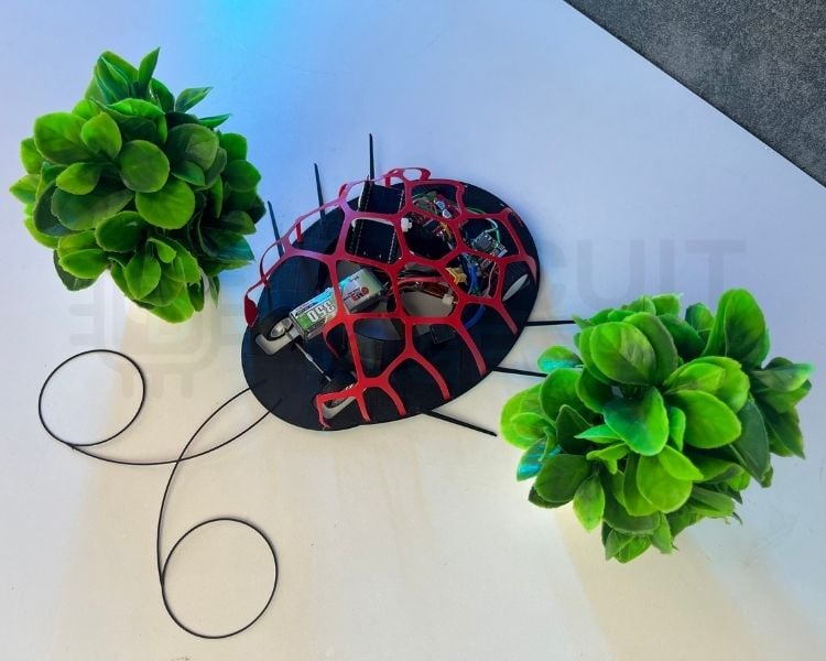
Despite its compact size, the robot generates more than 360 grams of holding force, weighs only around 104 grams, and is capable of climbing walls and ceilings using only a single BLDC motor for suction. The project also demonstrates an iterative engineering approach, where multiple failed prototypes ultimately led to a successful design. Along the way, techniques such as suction testing, lightweight optimization, AI-assisted concept visualization, Voronoi modelling, and mesh unfolding were combined to create a functional and visually unique beetle-inspired robot. In addition to this Beetle project, here is a collection related to robotics projects for reference.
Troubleshooting
Robot vibrating too much on the ceiling.
The cause is that the suction is not enough. You need to increase the suction by increasing the slider value in the web app, which keeps the beetle firm to the ceiling.
The BLDC motor restarts continuously and makes startup beep sequences and reboots.
The battery should be low, which is not able to provide enough power for the motor operation. Recharge your battery.
I built the robot, but it’s not sticking to walls or ceilings.
Check your wheel clearances. Keep the wheel diameter minimum so that the body to wall/ceiling distance is minimum.
Conclusion
This project shows that building a compact wall-climbing robot is not just about using a powerful motor, but it requires careful balancing of airflow, structural weight and mechanical design. By testing multiple enclosure designs, optimizing the body thickness, and developing a lightweight Voronoi-inspired shell, we were able to build a palm-sized robot capable of climbing walls and crawling across ceilings.
While there is still room for improvement, such as using a custom PCB, lighter electronics, and more advanced controls, this prototype serves as a solid foundation for future versions. It also demonstrates how we can turn a challenging idea into a working engineering project. Further, one can extend this project to make it a floor cleaning robot or a ceiling cleaning robot, just like this Arduino-based Vacuum Cleaner Robot that we have built some time back.
ESP32 Wall Climbing Robot GitHub
This repository provides the complete source code and documentation for building an ESP32-based wall-climbing robot. It enables users to replicate, modify, and enhance the robot's design and functionality for research and development.


Frequently Asked Questions
⇥ Can I add a battery with a much higher capacity?
Yes, but you need to maintain a balance between the battery weight and the max suction that the motor provides.
⇥ How long can I run the robot?
Currently, this robot gives a runtime of around 8 minutes. It can be further enhanced by a much optimised design, a better battery or a BLDC motor.
⇥ Can it climb up rough terrains?
Yes, it can climb up rough or normal terrains with ease.
DIY Robotics Projects You Can Build Today
Take your robotics skills to the next level with step-by-step guides for building a spider robot, a biped walking robot, and a Bluetooth robot car using Arduino and ESP32.

Designing and Controlling Quadruped Spider Robot with ESP32
One such remarkable creation is the spider robot. It can also be known as a quadruped robot due to its four legs. This innovative robotic project aims to emulate the locomotion and behaviour of spiders.

Biped Catbot: Walking and Dancing Robot using Arduino
Catbot, the star of our project, is a remarkable two-legged robot built on the Arduino Nano. It utilises five servo motors, with two dedicated to each leg and one controlling its head movements. Additionally, it employs an ultrasonic sensor to detect obstacles and navigate around them.

DIY Arduino Bluetooth Car Controlled by Mobile Application
This robot car can be controlled wirelessly with Bluetooth and an Android app, and other than that, we have placed RGB Neopixel LEDs on the front, back, and bottom of the robot to make it look cool.
Complete Project Code
#include <WiFi.h>
#include <WebServer.h>
const char* ssid = "your_ssid";
const char* password = "your-password";
WebServer server(80);
// ESC
const int escPin = 4;
const int pwmFreq = 50;
const int pwmResolution = 16;
// MX1508
const int L1 = 16;
const int L2 = 17;
const int R1 = 18;
const int R2 = 19;
bool bldcEnabled = false;
int throttle = 0;
uint32_t usToDuty(uint16_t us)
{
 uint32_t maxDuty = (1UL << pwmResolution) - 1;
 return (uint32_t)((us / 20000.0) * maxDuty);
}
void setThrottle(int percent)
{
 if (!bldcEnabled)
 {
   ledcWrite(escPin, usToDuty(1000));
   return;
 }
 percent = constrain(percent, 0, 100);
 uint16_t pulse =
     map(percent, 0, 100, 1000, 2000);
 ledcWrite(escPin, usToDuty(pulse));
}
// --------------------
// Robot Movement
// --------------------
void stopRobot()
{
 digitalWrite(L1, LOW);
 digitalWrite(L2, LOW);
 digitalWrite(R1, LOW);
 digitalWrite(R2, LOW);
}
void forward()
{
 digitalWrite(L1, HIGH);
 digitalWrite(L2, LOW);
 digitalWrite(R1, HIGH);
 digitalWrite(R2, LOW);
}
void backward()
{
 digitalWrite(L1, LOW);
 digitalWrite(L2, HIGH);
 digitalWrite(R1, LOW);
 digitalWrite(R2, HIGH);
}
void left()
{
 digitalWrite(L1, LOW);
 digitalWrite(L2, HIGH);
 digitalWrite(R1, HIGH);
 digitalWrite(R2, LOW);
}
void right()
{
 digitalWrite(L1, HIGH);
 digitalWrite(L2, LOW);
 digitalWrite(R1, LOW);
 digitalWrite(R2, HIGH);
}
void handleRoot()
{
 String page = R"rawliteral(
<!DOCTYPE html>
<html>
<head>
<meta name="viewport" content="width=device-width, initial-scale=1">
<style>
body{
   font-family:Arial;
   background:#f4f4f4;
   text-align:center;
}
h2{
   margin-top:20px;
}
.blueBtn{
   background:#007BFF;
   color:white;
   border:none;
   padding:15px 28px;
   font-size:18px;
   border-radius:8px;
   margin:8px;
   cursor:pointer;
}
.blueBtn:hover{
   background:#0056b3;
}
.slider{
   width:85%;
   margin-top:10px;
}
#val{
   color:#007BFF;
}
.controller{
   width:260px;
   margin:25px auto;
}
.row{
   display:flex;
   justify-content:center;
   margin:8px 0;
}
.ctrlBtn{
   width:80px;
   height:80px;
   font-size:18px;
   border:none;
   border-radius:12px;
   background:#4CAF50;
   color:white;
   cursor:pointer;
   margin:5px;
}
.stopBtn{
   background:#E53935;
}
.ctrlBtn:hover{
   opacity:0.85;
}
</style>
</head>
<body>
<h2>Wall Climbing Robot</h2>
<h3>BLDC Suction Control</h3>
<button class="blueBtn"
onclick="fetch('/bldcOn')">
ON
</button>
<button class="blueBtn"
onclick="fetch('/bldcOff')">
OFF
</button>
<br><br>
<input
type="range"
min="0"
max="100"
value="0"
class="slider"
id="speed">
<h2 id="val">0%</h2>
<hr>
<h3>Movement Control</h3>
<div class="controller">
   <div class="row">
       <button class="ctrlBtn"
       onclick="fetch('/forward')">
       FWD
       </button>
   </div>
   <div class="row">
       <button class="ctrlBtn"
       onclick="fetch('/left')">
       LEFT
       </button>
       <button class="ctrlBtn stopBtn"
       onclick="fetch('/stop')">
       STOP
       </button>
       <button class="ctrlBtn"
       onclick="fetch('/right')">
       RIGHT
       </button>
   </div>
   <div class="row">
       <button class="ctrlBtn"
       onclick="fetch('/backward')">
       BKWD
       </button>
   </div>
</div>
<script>
var slider=document.getElementById("speed");
var val=document.getElementById("val");
slider.oninput=function(){
   val.innerHTML=this.value+" %";
   fetch("/speed?value="+this.value);
}
</script>
</body>
</html>
)rawliteral";
 server.send(200, "text/html", page);
}
// --------------------
// Web Requests
// --------------------
void handleSpeed()
{
 throttle =
   server.arg("value").toInt();
 setThrottle(throttle);
 server.send(200, "text/plain", "OK");
}
void handleBLDCOn()
{
 bldcEnabled = true;
 setThrottle(throttle);
 server.send(200, "text/plain", "ON");
}
void handleBLDCOff()
{
 bldcEnabled = false;
 setThrottle(0);
 server.send(200, "text/plain", "OFF");
}
// --------------------
// Setup
// --------------------
void setup()
{
 Serial.begin(115200);
 Serial.println("Serial connected successfully!");
 pinMode(L1, OUTPUT);
 pinMode(L2, OUTPUT);
 pinMode(R1, OUTPUT);
 pinMode(R2, OUTPUT);
 stopRobot();
 ledcAttach(
   escPin,
   pwmFreq,
   pwmResolution);
 ledcWrite(
   escPin,
   usToDuty(1000));
 delay(5000); // arm ESC
 WiFi.begin(ssid, password);
 while(WiFi.status()!=WL_CONNECTED)
 {
   delay(500);
   Serial.print(".");
 }
 Serial.println();
 Serial.println(WiFi.localIP());
 server.on("/", handleRoot);
 server.on("/speed", handleSpeed);
 server.on("/bldcOn", handleBLDCOn);
 server.on("/bldcOff", handleBLDCOff);
 server.on("/forward",
   [](){ forward(); server.send(200); });
 server.on("/backward",
   [](){ backward(); server.send(200); });
 server.on("/left",
   [](){ left(); server.send(200); });
 server.on("/right",
   [](){ right(); server.send(200); });
 server.on("/stop",
   [](){ stopRobot(); server.send(200); });
 server.begin();
}
void loop()
{
 server.handleClient();
}

Add a comment
No account needed. Your comment appears once a moderator has reviewed it.