
Welcome to our latest project, an exciting journey where we delve into the world of robotics to construct a small DIY biped robot capable of walking and dancing. Meet Catbot, our charismatic bipedal robot, and join us in this innovative experiment that combines 3D printing, Arduino technology, and servo motors.
Our primary objective is to provide you with hands-on experience in creating small hobbyist robots using Arduino and mastering the art of servo motor programming for a multitude of applications. By the end of this project, you'll have the knowledge and skills to bring Catbot to life, enabling it to perform predefined walking and dancing routines.
Moreover, we'll equip you with a versatile program, featured at the end of this tutorial, allowing you to effortlessly customize your robot's actions. You can control the positions of the servo motors through the Serial monitor, giving you full creative control over your very own robot.
For making our robot to look really cool and fancy, I am using acrylic laser-cut parts. These parts not only enhance the project's visual appeal but also give it a classy touch to the final product. However, if you don't have access to these materials, don't worry! You can opt for online services or even use cardboard to achieve the same result.
Catbot, the star of our project, is a remarkable two-legged robot built on the Arduino Nano. It utilizes five servo motors, with two dedicated to each leg and one controlling its head movements. Additionally, it employs an ultrasonic sensor to detect obstacles and navigate around them.
Now, let's dive into the fascinating world of building and programming Catbot, your very own bipedal robot. And if this is not the robot your are looking for, we have a completely dedicated Robotics section where you can find many kinds of robots including self balancing robot, biped robot, vacuum cleaning robot etc.
Design and Build of Biped Robot
I created the custom Biped robot design specifically for this project, and you can see screenshots of the CAD design I made using Onshape, as well as the actual Robot I built, in the images below.

If you're interested in recreating this project or incorporating my design into your own work, I've included the CAD .dxf files, which you can download here.

For constructing this Robot, I used laser-cut acrylic parts. However, if you have access to a 3D printer, you can also use that. If you opt for the 3D printing route, you'll need to download the .stl file format from the same above link.
Here's a visual representation of what the laser-cut acrylic sheet will look.

The Arduino Nano Biped Catbot, like many other robots, gets judged by how flexible it is. This is often measured by something called "degrees of freedom" or DOF. Imagine DOF as the number of ways the robot can bend and move its parts. It's kind of like counting the different moves in a dance.
This robot comes in a flat-pack kit, and you don't need to do much soldering (melting metal to connect parts) to put it together and make it work. It has 4 special motors called SG90 servos, and they give it four different ways to move around. It can go forward, backward, to the right, and to the left.
Let me explain each part's movement:
The "Head" can rotate up to 180°, depending on the type of servo used for head rotation.
The "Hip" on the left and right sides can tilt the robot vertically to the right and left.
The "Foot" on the left and right sides move the feet up and down, allowing the robot to move forward.

Components needed for Biped Robot
Arduino Nano
SG 90 metal gear Servo motors (5x)
HC-SR04 Ultrasonic Sensor
Laser cut Acrylic Robot parts
7.4V Li-ion battery
Switch
Jumper wires
Breadboard or PCB (Printed Circuit Board)
Screws, nuts, spacers
Assembly of Biped Robot
We have utilized an acrylic sheet cut with a laser to create a Biped Robot for our project. The sheet has been precisely cut to accommodate all the necessary fittings and components, allowing for easy assembly using screwdrivers.
Before starting the assembly, we need to adjust the angle adjustment of the servo motors. Otherwise, your Biped Robot will not work properly.
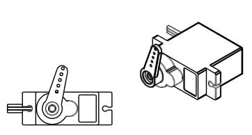
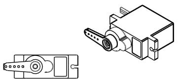
To begin, attach the Servo Arm to the servo by carefully aligning and securing it in place. We can manually calibrate and adjust the servo motor angle but sometimes manually calibration is not accurate or may not be possible. so you can calibrate your servo motors using the provided code #1. Refer to the circuit diagram mentioned below and connect your servo motors to Arduino. Upload the provided code #1 to your Arduino board, which will facilitate the calibration process. Failing to execute this step may result in unstable performance of your robot.
By ensuring proper alignment and calibration of the servos, you lay the foundation for a stable and well-functioning robot. After done with All servo’s 90° adjustments, you can pass leg Assembly stages.
Circuit Diagram for Biped Catbot with Arduino Nano (5 Servo Motors)
In this biped robot setup, the servo motors play a crucial role as pivotal joints for the robot's legs, allowing it to turn and swing at the Hip, turn or lower its Foot, and featuring one servo motor to rotate its head.

For this project, you don't need any complicated wiring because all the motors use 5V. We control the motors using digital pins. We didn't use the 5V pin on the Arduino because it wouldn't give enough power to run all the motors well. Instead, we use a different power supply. This way, we can provide enough power to make sure all the motors work properly.
Note: Always turn off the Arduino power switch when you upload the code.
Circuit Connection:
Connect the Arduino Nano to the breadboard or PCB. Make sure to connect the power and ground pins.
Connect the 7.4V Li-ion battery to the Vin pin of the Arduino Nano via a switch. This switch allows you to turn the Arduino on and off from external supply.
Connect the ultrasonic sensor to the Arduino Nano:
VCC (Power) of the sensor to 5V on the Arduino.
GND (Ground) of the sensor to GND on the Arduino.
TRIG (Trigger) pin of the sensor to a Analog pin on the Arduino Nano, e.g., A5.
ECHO (Echo) pin of the sensor to another Analog pin on the Arduino Nano, e.g., A3.
Connect the SG90 servo motors to the Arduino Nano for controlling the robot's movements: Each servo has three wires power (red), ground (brown), and signal (orange). Connect the power wires to the positive terminal of your power source (battery), the ground wires to the negative terminal, and the signal wires to specific digital pins on the Arduino Nano.
Servo 1: Head movement (e.g., Digital Pin 3)
Servo 2: Left Leg (e.g., Digital Pin 5)
Servo 3: Right Leg (e.g., Digital Pin 9)
Servo 4: Left Foot (e.g., Digital Pin 7)
Servo 5: Right Foot (e.g., Digital Pin 11)
Secure all components to the robot's frame using screws, nuts, and spacers as needed. Ensure that all connections are secure and free from loose wires or potential short circuits. Always double-check your connections before powering on the circuit.
Biped Catbot Code Explanation
Arduino code that controls a bipedal robot using servos and an ultrasonic sensor for distance measurement. The code includes functions to control various movements of the robot, such as forward walking, turning, tilting, and swinging. Additionally, the code uses the NewPing library to interface with the ultrasonic sensor and measure distances.
It is important to execute this code #1 before starting the assembly stages. This code is designed to calibrate and adjust the servo motors to their correct angles. By running this code, you can ensure that the servo motors are properly functioning and positioned accurately. This will help prevent any potential issues or complications during the subsequent stages of the assembly process.
Code #1
#include <Servo.h>    // include servo library
// Define 5 Servos
Servo myServo1; // Head Servo
Servo myServo2; // Left Hip Servo
Servo myServo3; // Left foot Servo
Servo myServo4; // Right Hip Servo
Servo myServo5; // Right foot Servo
void setup() {
  // Attach servos to Arduino PWM Pins
  myServo1.attach(3);
  myServo2.attach(5);
  myServo3.attach(7);
  myServo4.attach(9);
  myServo5.attach(11);
  myServo1.write(90);
  myServo2.write(90);
  myServo3.write(90);
  myServo4.write(90);
  myServo5.write(90);
}
 void loop() {
}
This code #2 includes all the necessary servo motor movements to make your robot functional. Without this code, you will not be able to complete the project successfully. It is crucial for the proper operation of the robot.
At the end of this tutorial, you'll find the full program for your robot. Below, I'll break down the different parts of the program for you. This program has the ability to control your robot's actions. You can also customize its movements by adjusting the tilt angle, turn angle, and swing angle for each individual motor to suit your calibration needs.
#include <Servo.h>
#include <NewPing.h>
These lines include the necessary libraries. The Servo.h library provides functionalities to control servo motors, while the NewPing.h library facilitates communication with the ultrasonic sensor.
// edit the pin according to your connection
#define ECHO_PIN     A3  // Arduino pin tied to echo pin on the ultrasonic sensor.
#define TRIGGER_PIN  A5 // Arduino pin tied to trigger pin on the ultrasonic sensor.
#define LEFTLEG       5
#define RIGHTLEG     9
#define LEFTFOOT      7
#define RIGHTFOOT     11
#define  HEAD          3
#define MAX_DISTANCE 200 // Maximum distance we want to ping for (in centimeters). Maximum sensor distance is rated at 400-500cm.
int Min_DISTANCE = 10;
Here, the code defines pin assignments for various components. The ECHO_PIN and TRIGGER_PIN are assigned to the echo and trigger pins of the ultrasonic sensor, respectively. The LEFTLEG, RIGHTLEG, LEFTFOOT, RIGHTFOOT, and HEAD pins are used for the servos controlling different parts of the robot. MAX_DISTANCE is set as the maximum distance the ultrasonic sensor can measure.
NewPing sonar(TRIGGER_PIN, ECHO_PIN, MAX_DISTANCE); // NewPing setup of pins and maximum distance.
This line creates an instance of the NewPing class named sonar, which is used to communicate with the ultrasonic sensor. It is initialized with the trigger and echo pin numbers and the maximum distance.
Servo Lleg;
Servo Rleg;
Servo Lfoot;
Servo Rfoot;
Servo Head;
Instances of the Servo class are created for each servo motor that controls different parts of the robot. These instances are Lleg, Rleg, Lfoot, Rfoot, and Head.
int Hcenter = 90;
int RLcenter = 90;
int RFcenter = 90;
int LLcenter = 90;
int LFcenter = 90;
These variables store the servo positions that correspond to the centered or default positions for the servos controlling the head, right leg, left leg, right foot, and left foot.
int tAngle = 20;    // tilt angle
int uAngle = 25;    // turn angle
int sAngle = 25;    // swing angle
int Speed = 50;    // Speed of walk
These variables store various angles and speed settings used for controlling the robot's movements. tAngle stores the tilt angle, uAngle stores the turn angle, sAngle stores the swing angle, and Speed stores the delay between servo movements.
void Forward(byte Steps, byte Speed){
  Serial.println("Forward");
  TiltRightUp(tAngle, Speed);
  for (byte j=0; j<Steps; ++j){
    SwingRight(sAngle, Speed);
    TiltRightDown(tAngle, Speed);
    TiltLeftUp(tAngle, Speed);
    SwingRcenter(sAngle, Speed);
    SwingLeft(sAngle, Speed);
    TiltLeftDown(tAngle, Speed);
    TiltRightUp(tAngle, Speed);
    SwingLcenter(sAngle, Speed);
  }
  TiltRightDown(tAngle, Speed);
}
This function is defined to make the robot walk forward. It takes two arguments: Steps (the number of steps to take) and Speed (the delay between servo movements). The function uses various sub-functions to create a walking pattern: SwingRight, TiltRightUp, TiltRightDown, TiltLeftUp, SwingRcenter, SwingLeft, TiltLeftDown, and TiltRightUp. These sub-functions are called in sequence to create the walking motion.
void TurnLeft(byte Steps, byte Speed){
  Serial.println("TurnLeft");
  TiltLeftUp(uAngle, Speed);
  delay(20);
  for (byte j=0; j<Steps; ++j){
    LeftLegIn(sAngle, Speed);
    TiltLeftDown(uAngle, Speed);
    TiltRightUp(uAngle, Speed);
    delay(20);
    LeftLegIcenter(sAngle, Speed);
    RightLegOut(sAngle, Speed);
    TiltRightDown(uAngle, Speed);
    TiltLeftUp(uAngle, Speed);
    delay(20);
    RightLegOcenter(sAngle, Speed);
  }
  TiltLeftDown(uAngle, Speed);
}
Similarly, this function is defined to make the robot turn left. It uses a combination of sub-functions to achieve a turning motion: TiltLeftUp, LeftLegIn, TiltLeftDown, TiltRightUp, LeftLegIcenter, RightLegOut, TiltRightDown, and TiltLeftUp.
void TurnRight(byte Stps, byte Speed){
  Serial.println("TurnRight");
  TiltRightUp(uAngle, Speed);
  delay(20);
  for (byte f=0; f<=Stps; ++f){
    RightLegIn(sAngle, Speed);
    TiltRightDown(uAngle, Speed);
    TiltLeftUp(uAngle, Speed);
    delay(20);
    RightLegIcenter(sAngle, Speed);
    LeftLegOut(sAngle, Speed);
    TiltLeftDown(uAngle, Speed);
    TiltRightUp(uAngle, Speed);
    delay(20);
    LeftLegOcenter(sAngle, Speed);
  }
  TiltRightDown(uAngle, Speed);
}
This function is defined to make the robot turn right. It uses sub-functions in a sequence similar to the TurnLeft function but with movements on the opposite side.
void HeadRight() {
  Serial.println("HeadRight");
  Head.write(Hcenter - 105);
  delay(1000);
}
void HeadLeft() {
  Serial.println("HeadLeft");
  Head.write(Hcenter + 105);
  delay(1000);
}
void HeadCenter() {
  Serial.println("HeadCenter");
  Head.write(Hcenter);
  delay(1000);
}
These functions control the robot's head movement. HeadRight and HeadLeft turn the head to the right and left, respectively, by adjusting the angle of the Head servo. HeadCenter centers the head by setting the Head servo to its default angle.
void TiltRightUp(byte ang, byte sp){
  //tilt right up
  for (int i=0; i<=ang; i+=5){
    Lfoot.write(LFcenter+i);
    Rfoot.write(RFcenter+i);
    delay(sp);
  }
}
void TiltRightDown(byte ang, byte sp){
  //tilt right down
  for (int i=ang; i>0; i-=5){
    Lfoot.write(LFcenter+i);
    Rfoot.write(RFcenter+i);
    delay(sp);
  }
}
void TiltLeftUp(byte ang, byte sp){
  //tilt left up
  for (int i=0; i<=ang; i+=5){
    Lfoot.write(LFcenter-i);
    Rfoot.write(RFcenter-i);
    delay(sp);
  }
}
void TiltLeftDown(byte ang, byte sp){
  //tilt left down
  for (int i=ang; i>0; i-=5){
    Lfoot.write(LFcenter-i);
    Rfoot.write(RFcenter-i);
    delay(sp);
  }
}
These functions control tilting movements of the robot's legs and feet. The functions increment or decrement the servo angles in steps to achieve tilting motions.
void LeftFootUp(char ang, byte sp){
  //tilt left up
  for (int i=0; i<=ang; i+=5){
    Lfoot.write(LFcenter-i);
    delay(sp);
  }
}
void LeftFootDown(byte ang, byte sp){
  //tilt left down
  for (int i=ang; i>0; i-=5){
    Lfoot.write(LFcenter-i);
    delay(sp);
  }
}
void RightFootUp(byte ang, byte sp){
  //tilt right up
  for (int i=0; i<=ang; i+=5){
    Rfoot.write(RFcenter+i);
    delay(sp);
  }
}
void RightFootDown(byte ang, byte sp){
  //tilt right down
  for (int i=ang; i>0; i-=5){
    Rfoot.write(RFcenter+i);
    delay(sp);
  }
}
Similarly, these functions control the raising and lowering of the robot's feet by adjusting the servo angles.
void SwingRight(byte ang, byte sp){
  //swing right
  for (int i=0; i<=ang; i+=5){
    Lleg.write(LLcenter-i);
    Rleg.write(RLcenter-i);
    delay(sp);
  }
}
void SwingRcenter(byte ang, byte sp){
  //swing r->center
  for (int i=ang; i>0; i-=5){
    Lleg.write(LLcenter-i);
    Rleg.write(RLcenter-i);
    delay(sp);
  }
}
void SwingLeft(byte ang, byte sp){
  //swing left
  for (byte i=0; i<=ang; i=i+5){
    Lleg.write(LLcenter+i);
    Rleg.write(RLcenter+i);
    delay(sp);
  }
}
void SwingLcenter(byte ang, byte sp){
  //swing l->center
  for (byte i=ang; i>0; i=i-5){
    Lleg.write(LLcenter+i);
    Rleg.write(RLcenter+i);
    delay(sp);
  }
}
These functions control the swinging motion of the robot's legs. The SwingRight and SwingLeft functions move the legs outward, while SwingRcenter and SwingLcenter move them back to the center.
void RightLegIn(byte ang, byte sp){
  //swing right
  for (int i=0; i<=ang; i+=5){
    Rleg.write(RLcenter-i);
    delay(sp);
  }
}
void RightLegIcenter(byte ang, byte sp){
  //swing r->center
  for (int i=ang; i>0; i-=5){
    Rleg.write(RLcenter-i);
    delay(sp);
  }
}
void RightLegOut(byte ang, byte sp){
  //swing right
  for (int i=0; i<=ang; i+=5){
    Rleg.write(RLcenter+i);
    delay(sp);
  }
}
void RightLegOcenter(byte ang, byte sp){
  //swing r->center
  for (int i=ang; i>0; i-=5){
    Rleg.write(RLcenter+i);
    delay(sp);
  }
}
These functions control the movement of the robot's right leg. RightLegIn and RightLegOut move the leg inwards and outwards, respectively. RightLegIcenter and RightLegOcenter move the leg back to the center position from the respective positions.
void LeftLegIn(byte ang, byte sp){
  //swing left
  for (byte i=0; i<=ang; i=i+5){
    Lleg.write(LLcenter+i);
    delay(sp);
  }
}
void LeftLegIcenter(byte ang, byte sp){
  //swing l->center
  for (byte i=ang; i>0; i=i-5){
    Lleg.write(LLcenter+i);
    delay(sp);
  }
}
void LeftLegOut(byte ang, byte sp){
  //swing left
  for (byte i=0; i<=ang; i=i+5){
    Lleg.write(LLcenter-i);
    delay(sp);
  }
}
void LeftLegOcenter(byte ang, byte sp){
  //swing l->center
  for (byte i=ang; i>0; i=i-5){
    Lleg.write(LLcenter-i);
    delay(sp);
  }
}
These functions control the movement of the robot's left leg in a similar manner as the RightLeg functions.
These functions define the detailed movements and patterns of the bipedal robot's motion. They use the servo angles and delay times to create specific motions, such as walking, turning, and tilting. The behaviors are created by sequencing these sub-functions appropriately in the higher-level movement functions like Forward, TurnLeft, and TurnRight.
void setup() {
  Serial.begin(19200);
  Serial.println("Bipedino setup is running.");
  Lleg.attach(LEFTLEG);
  Rleg.attach(RIGHTLEG);
  Lfoot.attach(LEFTFOOT);
  Rfoot.attach(RIGHTFOOT);
  Head.attach(HEAD);
  CenterServos();
  delay(500);
  for (int i = 0; i < 5; ++i) {
    GetSonar();
    delay(1000);
  }
  Serial.println("Bipedino is ready.");
}
In simple terms, what this code does in the setup() function is:
We set up communication with your computer via a serial connection. Attach servo motors to specific pins on the Arduino for control. Position the servos at their starting points. Calibrate the ultrasonic sensor by taking measurements. Indicate that the setup is complete and the robot is ready to run.
void loop() {
  unsigned int cmCenter = MAX_DISTANCE;
  unsigned int cmLeft   = MAX_DISTANCE;
  unsigned int cmRight  = MAX_DISTANCE;
  HeadCenter();
  cmCenter = GetSonar();
  if (cmCenter < Min_DISTANCE) {
    HeadRight();
    cmRight = GetSonar();
    HeadCenter();
    if (cmRight > Min_DISTANCE) {
      TurnRight(5, 50);
    } else {
      HeadLeft();
      cmLeft = GetSonar();
      HeadCenter();
      if (cmLeft > Min_DISTANCE) {
        TurnLeft(5, 50);
      }
    }
  } else {
    int nSteps = cmCenter / 5;
    if (nSteps > 5) {
      nSteps = 5;
    }
    else {
      nSteps = 1;
    }
    Serial.print("Steps <");
    Serial.print(nSteps);
    Serial.println(">");
    for (int n = 0; n < nSteps; n++) {
      Forward(1,50);
    }
  }
}
This loop() function repeatedly checks the distance in front of the robot using the ultrasonic sensor and makes decisions on whether to turn or move forward based on the detected obstacles. If an obstacle is detected very close, the robot will turn to find an open path. Otherwise, it will take a certain number of steps forward based on the detected distance.
int GetSonar() {
  unsigned int uS = sonar.ping(); // Send ping, get ping time in microseconds (uS).
  Serial.print("Ping: ");
  Serial.print(uS / US_ROUNDTRIP_CM); // Convert ping time to distance and print   result (0 = outside set distance range, no ping echo)
  Serial.println("cm");
  return uS / US_ROUNDTRIP_CM;
}
This function uses an ultrasonic sensor (sonar) to measure distances. It sends a ping and calculates the time it takes for the ping to bounce back. It then converts this time into distance in centimeters, prints the result, and returns the distance.
void CenterServos() {
  Lleg.write(LLcenter);      // tell servo to go to position in variable 'center'
  Rleg.write(RLcenter);      // tell servo to go to position in variable 'center'
  Lfoot.write(LFcenter);     // tell servo to go to position in variable 'center'
  Rfoot.write(RFcenter);     // tell servo to go to position in variable 'center'
  Head.write(Hcenter);        // tell servo to go to position in variable 'center'
  delay(1000);               // waits 100ms for the servos to reach the position
}
This function positions the servo motors for the legs, feet, and head of the robot to their center positions. It then adds a delay to allow the servos to reach these positions.
Conclusion
In conclusion, the Biped Catbot project represents a fascinating journey into the world of robotics and Arduino-based automation. Throughout this project, we've learned how to assemble and program a small, two-legged robot capable of walking, dancing, and avoiding obstacles.
This project allowed you to personalize the robot's movements by adjusting angles, fostering creativity in your robot design. Whether using acrylic or cardboard, customization is key. By completing this project, you've gained valuable insights into robotics, improved programming skills, and gained the confidence to pursue further robotic endeavors. Let your creativity soar and keep building incredible robots.
