 Anand D
Author

In this project, we’ll be learning how to build an ESP32 Speech to Text system using an ESP32 development board. We’ll use an I2S MIC to record speech and an OLED display to display the converted text. In addition to the display, the text will also appear in the serial monitor. Since ESP32 cannot run a Speech recognition model locally due to its hardware limitations, we will be using a cloud-based service for this resource-intensive task. The service is called Wit.ai. We have several other cloud platforms as well that can be used to implement Offline Voice Recognition, like Edge Impulse.
Here, the I2S MIC captures audio, and the ESP32 sends the audio to Wit.ai for processing. Wit.ai sends back the extracted text in JSON format to the ESP32. ESP32 then displays the received text in the OLED display as well as the serial monitor. No special ESP32 STT library is required beyond the standard ESP32 Arduino Core and a Wi-Fi connection. This is one of the more advanced ESP32 projects that combines audio hardware, Wi-Fi networking, and a cloud API in a single build.
Quick Answer - How does ESP32 speech-to-text work?
The INMP441 I2S microphone captures audio and streams it as 16-bit PCM data at 16 kHz to the ESP32. The ESP32 sends this audio over Wi-Fi to the Wit.ai cloud API via HTTPS. Wit.ai processes the audio using NLP and returns the recognised text as JSON. The ESP32 parses the JSON and displays the text on an OLED screen
Table of Contents
- What Is Wit.ai and Why Use It for ESP32 Speech-to-Text?
- Key Reasons Developers Choose Wit.ai for ESP32 Projects
- Block Diagram
- Components Required
- Circuit Diagram
- Wit.ai Account Setup
- Required Arduino Libraries
- Code Full Explanation
- Uploading the Code and Testing
- Testing the Circuit
- Troubleshooting
- GitHub Repository
What Is Wit.ai and Why Use It for ESP32 Speech-to-Text?
Wit.ai is a cloud-based platform developed by Meta. You can log in to Wit.ai using your Meta account if you have one - that means the account that you use to log in to Facebook / Instagram. Wit.ai can be used to do Speech-to-Text as well as Text-to-Speech.
How this platform works is very easy. We need to send the audio that we need to be converted to Wit.ai in a digital form. The I2S MIC that’s used in this project outputs audio in the form of a digital signal, so it's easy for us to feed the digital audio to the ESP32 for processing. This digital audio reaches Wit.ai, and it converts the audio to text and sends back the text to the ESP32 in JSON format. Natural Language Processing (NLP) is what sits behind Wit.ai to make it understand the context of the received audio. Wit.ai is used widely to build bots, mobile apps, and smart home devices that involve ESP32 speech-to-text projects. They have also provided a detailed documentation on how to get started with Wit.ai
Key Reasons Developers Choose Wit.ai for ESP32 Projects
Wit.ai is widely used around the world because it:
- Is easy to integrate with APIs
- It’s free to use as per their terms and conditions.
- Requires no high-end hardware (processing is cloud-based)
- Offers detailed documentation and a developer’s guide.
- Supports both simple and advanced AI-based applications
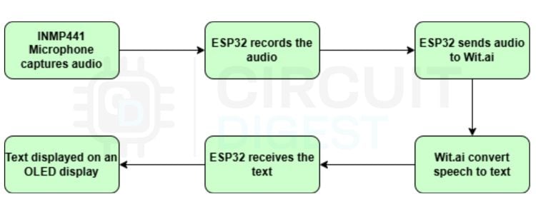
How the ESP32 Speech-to-Text System Works - Block Diagram
The block diagram illustrates the working of the ESP32 Speech-to-Text system. It has an ESP32, its peripherals and Wit.ai. Initially, the INMP441 I2S microphone captures the user’s voice input in real time. ESP32 uses the I2S protocol to read digital audio from the microphone. The audio is converted into a mono-channel 16-bit PCM audio with a 16 kHz sample rate. Once the audio is captured, the ESP32 sends the raw audio data over Wi-Fi to Wit.ai. Since we are using Wi-Fi to connect to the cloud service, this works online only. If you are interested in ESP32 Text to Speech offline, you can refer to our ESP32 Text to Speech Offline System.
Now, Wit.ai processes this audio and converts it into text, which is then sent back to the ESP32 as JSON. ESP32 then extracts the words from the response and displays them in the OLED display.
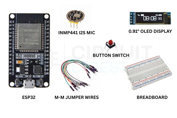
Components Required for ESP32 Speech-to-Text Using AI
The following are the main components that are required to build this project.
| S No | Item | Quantity | Description |
| 1 | ESP32 | 1 | Acts as the central controller of the whole circuit |
| 2 | INMP441 12S MIC | 1 | To record audio |
| 3 | Switch | 1 | To turn on the listening mode |
| 4 | 0.91” OLED Display | 1 | To display the converted test |
| 5 | M-M Jumper Wires | 10 | To make connections |
| 6 | Breadboard | 1 | To assemble the circuit |
Circuit Diagram - ESP32 Speech to Text Wiring
Following is the whole circuit for this project.

You can see that we have the ESP32 development board in the centre of the circuit. You can see the pin connections of the Microphone, OLED display and the Button switch with ESP32 in the tables listed below.
INMP441 I2S Microphone Pin Connections to ESP32
0.91-inch OLED Display (SSD1306 I2C) Pin Connections to ESP32
The whole circuit was assembled in a breadboard using some Male-Male jumper cables. You can design your own PCB or assemble them in a dotted PCB - as per your convenience and interest, the circuit connections remain the same. You can connect an external 3.7V battery to the system to make it handy. Just connect the battery terminals to the VIN and GND of the ESP32.
You need to press the button to keep it in “Listening mode”. The device then listens to speeches and displays them in the OLED display in real time.
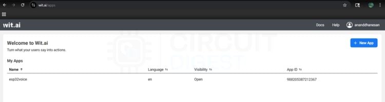
Wit.ai Account Setup - Getting Your Service Access Token
Go to https://wit.ai > Login with your Meta account > Click ‘+ New App’
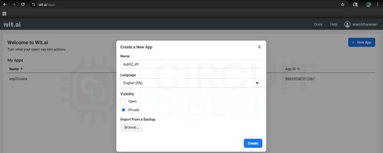
Give the app a Name. You can set the visibility as Private for any personal projects and Open for public projects, which means if we target a wide range of users, and click Create
From the side menu, go to Management > Settings > Copy the Service Access Token
Required Arduino Libraries for ESP32 Speech to Text
This project uses the following libraries. The first four are part of the standard ESP32 Arduino Core and require no separate installation. The last two must be installed manually via the Arduino IDE Library Manager
| Library | Source | Purpose |
WiFi.h | ESP32 Core (built-in) | Wi-Fi connection management |
WiFiClientSecure.h | ESP32 Core (built-in) | HTTPS / TLS connection to Wit.ai API |
driver/i2s.h | ESP32 Core (built-in) | I2S driver for INMP441 microphone |
Wire.h | ESP32 Core (built-in) | I2C communication for OLED |
Adafruit_GFX.h | Arduino Library Manager | Graphics primitives for OLED display |
Adafruit_SSD1306.h | Arduino Library Manager | SSD1306 OLED driver |
ESP32 Speech to Text Code - Full Explanation
Below is the complete Arduino sketch for this ESP32 speech-to-text using AI project, broken down section by section.
1. Include Libraries and Define Credentials
#include <WiFi.h>
#include <WiFiClientSecure.h>
#include <driver/i2s.h>
#include <Wire.h>
#include <Adafruit_GFX.h>
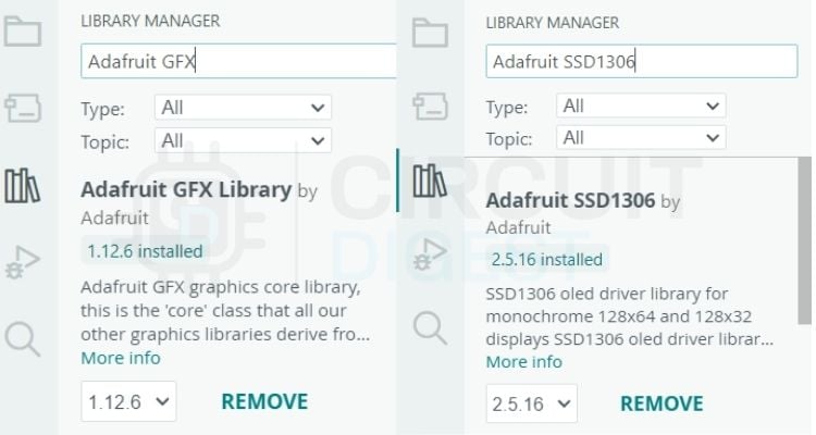
#include <Adafruit_SSD1306.h>Above are the libraries that we need for the ESP32 Speech-to-Text code to work. We need two external ESP32 speech-to-text libraries as well. The “Adafruit_GFX” and “Adafruit_SSD1306” from Adafruit. You can install them by going to the library manager in Arduino IDE and searching for them. Install the latest versions. You can refer to the image below to see if you have installed the right libraries. Rest libraries come preinstalled with the ESP32 Core.
// WiFi + Wit.ai
const char* ssid = "your_ssid";
const char* password = "your_password";
const char* service_access_token = "your_service_access_token";
Make sure you update the SSID with your own SSID, Password with your WiFi password and Service Access Token with the one that we copied from Wit.ai in the above step.
2. OLED Display Update Function
void updateDisplay(String message) {
 display.clearDisplay();
 display.setCursor(0, 0);
 display.println(message);
 display.display();
}
This function clears the OLED display contents and prints new messages.
3. I2S Microphone Initialisation
void setupI2S() {
 i2s_config_t config = {
   .mode = (i2s_mode_t)(I2S_MODE_MASTER | I2S_MODE_RX),
   .sample_rate = SAMPLE_RATE,
   .bits_per_sample = I2S_BITS_PER_SAMPLE_16BIT,
   .channel_format = I2S_CHANNEL_FMT_ONLY_RIGHT,
   .communication_format = I2S_COMM_FORMAT_STAND_I2S,
   .intr_alloc_flags = 0,
   .dma_buf_count = 8,
   .dma_buf_len = 512,
   .use_apll = false
 };
 i2s_pin_config_t pin_config = {
   .bck_io_num = I2S_SCK,
   .ws_io_num = I2S_WS,
   .data_out_num = -1,
   .data_in_num = I2S_SD
 };
 i2s_driver_install(I2S_PORT, &config, 0, NULL);
 i2s_set_pin(I2S_PORT, &pin_config);
}
This function initialises the I2S microphone communication
4. Core Function — Stream Audio to Wit.ai and Parse Response
void sendAudioToWit() {
 WiFiClientSecure client;
 client.setInsecure();
 if (!client.connect("api.wit.ai", 443)) {
   updateDisplay("Conn Failed");
   return;
 }
 String header = "POST /speech?v=20230215 HTTP/1.1\r\n"
                 "Host: api.wit.ai\r\n"
                 "Authorization: Bearer " + String(service_access_token) + "\r\n"
                 "Content-Type: audio/raw;encoding=signed-integer;bits=16;rate=16000;endian=little\r\n"
                 "Transfer-Encoding: chunked\r\n"
                 "Connection: close\r\n\r\n";
 client.print(header);
 updateDisplay("Listening...");
 size_t bytes_read;
 while (digitalRead(BUTTON_PIN) == LOW) {
   i2s_read(I2S_PORT, buffer, sizeof(buffer), &bytes_read, portMAX_DELAY);
   if (bytes_read > 0) {
     client.printf("%X\r\n", bytes_read);
     client.write((uint8_t*)buffer, bytes_read);
     client.print("\r\n");
   }
 }
 client.print("0\r\n\r\n");
 updateDisplay("Processing...");
 String finalResult = "";
 while (client.connected() || client.available()) {
   if (client.available()) {
     String line = client.readStringUntil('\n');

     // Look for the "text" key.
     // Wit.ai sends partials first, then the full text last.
     // We keep updating finalResult so it holds the VERY last one received.
     int textIndex = line.indexOf("\"text\": \"");
     if (textIndex != -1) {
       int start = textIndex + 9;
       int end = line.indexOf("\"", start);
       finalResult = line.substring(start, end);
     }
   }
 }
 client.stop();
 if (finalResult != "") {
   updateDisplay(finalResult);
   Serial.println("Final: " + finalResult);
 } else {
   updateDisplay("No speech detected");
 }
}
This is the core function of the project. It creates a secure HTTPS connection with Wit.ai. It contains details about the Authorisation token, Audio format and Sample rate. This is where the major actions happen. Audio is read from the microphone, stored in a buffer and streamed to Wit.ai in real time. This is the heart of the speech-to-text conversion using ESP32.
5. Setup and Loop Functions
void setup() {
 Serial.begin(115200);
 pinMode(BUTTON_PIN, INPUT_PULLUP);
 // Initialize OLED
 if(!display.begin(SSD1306_SWITCHCAPVCC, 0x3C)) {
   Serial.println(F("SSD1306 allocation failed"));
   for(;;);
 }
 display.clearDisplay();
 display.setTextSize(1);
 display.setTextColor(WHITE);
 updateDisplay("Connecting...");
 WiFi.begin(ssid, password);
 while (WiFi.status() != WL_CONNECTED) { delay(500); }
This is the setup function, which runs only once. It initialises the serial communication, configures the input and output devices like the switch and the OLED display. Then it connects to a Wi-Fi network as well.
setupI2S();
updateDisplay("Ready.");
This function initialises the I2S microphone and displays “Ready” as the network is connected.
void loop() {
 if (digitalRead(BUTTON_PIN) == LOW) {
   sendAudioToWit();
   while(digitalRead(BUTTON_PIN) == LOW) delay(10);
   delay(200);
 }
}
This is the loop function that runs continuously after the setup() finishes
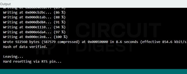
Once all the above steps are done, click the upload button. You’ll see the successfully uploaded message in the terminal screen below as follows.
Uploading the Code and Testing the ESP32 STT System
First, the code connects the ESP32 to Wi-Fi and initialises the OLED display and I2S microphone. The OLED screen displays ready once it's connected to Wi-Fi and ready to capture audio. Once we press the button, it displays “Listening”, and the sendAudioToWit() function opens a secure HTTPS connection to the Wit.ai API and continuously sends the microphone audio data in small chunks.
After the button is released, the ESP32 stops sending audio and waits for the JSON result from Wit.ai. The code scans the response for the "text" field, which contains the converted speech text. The recognised sentence is shown on the OLED display and printed to the Serial Monitor. If nothing is detected, it displays “No speech detected”. In simple terms, this project acts like a tiny voice assistant: press the button, speak into the microphone, and the spoken words appear as text on the OLED screen. If you like to learn Text-to-Speech using a basic Arduino and understand fundamentals with a simple Arduino code, you can check out our Arduino- based Text to Speech (TTS) Converter project, which has just 15 lines of code.
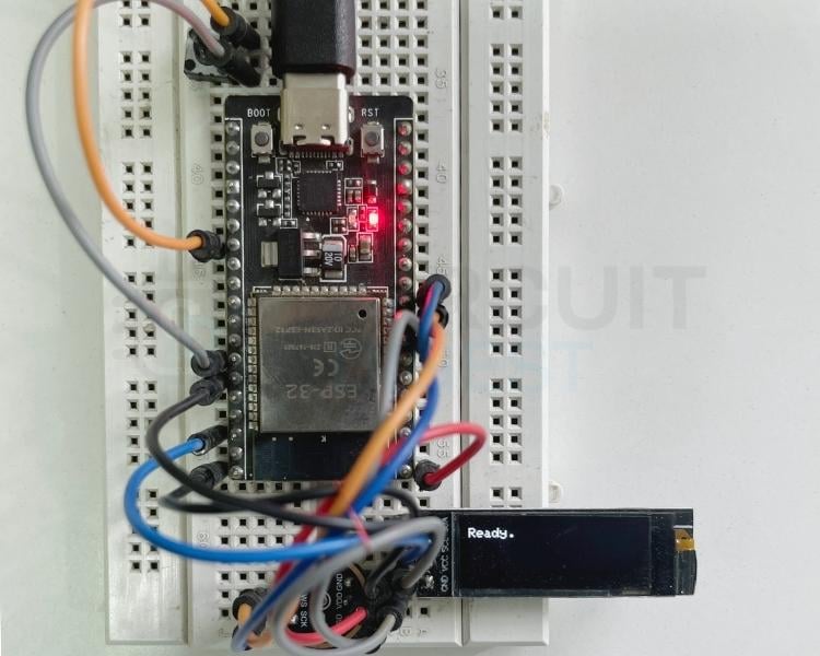
Testing the Circuit
- Once the circuit is powered on, you’ll see the device say Ready.
- You press the button - it shows “Listening” and records the speech.
- Release the button - it sends the audio to Wit.ai and displays the converted text in the OLED display in real time.
Troubleshooting the ESP32 Speech to Text Project
Make sure all the connections are firm so that it works efficiently. Initially, the display should show “Ready” before you push the button, and the device starts “Listening”. After this, you can push the button any number of times and test the device. Most issues with this ESP32 speech recognition project fall into four categories: wiring errors, missing libraries, Wi-Fi or API problems, and audio quality issues. The quick-reference table below covers the most common ones. Most issues with this ESP32 speech recognition project fall into four categories: wiring errors, missing libraries, Wi-Fi or API problems, and audio quality issues.
| Symptom | Likely Cause | Fix |
| Compile error: Adafruit_GFX.h not found | Missing library | Install Adafruit_GFX via Library Manager |
| OLED shows "Connecting…" indefinitely | Wrong SSID or password | Double-check Wi-Fi credentials in the sketch |
| OLED shows "Conn Failed" | Cannot reach api.wit.ai | Check internet access; verify firewall is not blocking port 443 |
| "No speech detected" is always shown | Mic wiring or wrong token | Check INMP441 GPIO pins; confirm Service Access Token is correct |
| Garbled or incorrect text | Background noise / speaking too far away | Speak clearly within 15–20 cm of the INMP441; reduce ambient noise |
| OLED shows nothing / all dark | Wrong I2C address or loose wiring | Confirm the OLED I2C address is 0x3C; check SDA/SCL connections to GPIO 21/22 |
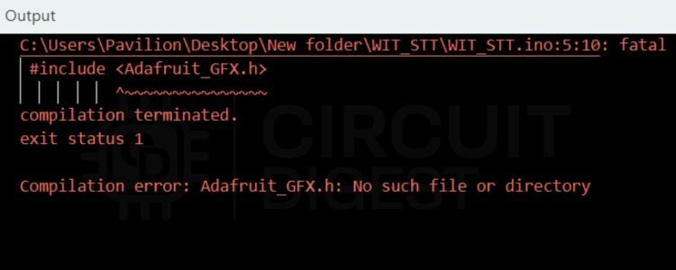
There is a chance that you may encounter some errors like this while uploading the code. These kinds of errors suggest that a library is missing. Here in this screenshot, the Adafruit_GFX library is missing. You can install it from the Library Manager by following the steps explained above.
Extending the ESP32 Speech to Text Project
Once you have the basic speech-to-text in ESP32 working, there are several natural directions to expand the project:
- After successfully creating a simple text-to-speech interface using the ESP32, you may wish to build upon its capabilities in the following areas:
- Voice Controlled Relay/GPIO Parse keywords from the text returned (as understood by the ESP32), then switch an output pin for controlling lights, fans and machines which could be connected directly to the ESP32.
- MQTT + Dashboard to publish that same transcription to an MQTT broker, such as the CircuitDigest Cloud and display it on a web-based IoT Dashboard.
- WhatsApp Notifications Transmit the interpreted speech (text) via the Arduino to a WhatsApp contact that you have previously configured in our Arduino WhatsApp Notification example project.
- Multi-language Recognition by changing the Wit.ai application's native language setting for recognising Indic languages, including Hindi and/or Tamil, as well as other Indian languages.
- Alternative to Wit.ai: If your application needs voice recognition without internet access, consider using Edge Impulse-based voice recognition on the ESP32 processor.
- Text-to-Speech Combined with our Arduino Text to Speech Converter to create a two-way voice user interface.
We have successfully built a working ESP32 Speech to Text system using the INMP441 I2S microphone, the Wit.ai cloud speech recognition API, and a 0.91-inch OLED display. If you want to go further in Artificial Intelligence, browse our collection of AI projects and tutorials covering machine learning, cloud APIs, and edge inference on microcontrollers
ESP32 Speech-to-Text GitHub Repository
You can get the full code from the ESP32 speech-to-text GitHub link provided below.


Frequently Asked Questions on ESP32 Speech to Text
1. What’s the best mic for speech recognition on an ESP32?
For ESP32 audio projects that use I2S, the INMP441 kind of ends up being the ideal choice, you know. It’s a digital MEMS microphone, so it outputs I2S PCM data straight away, which means you don’t need an ADC. It wants a 3.3V supply, it has low self-noise, and a decent range too; it can capture audio roughly from 60 Hz up to 15 kHz. And in practice, it’s super common; you can often find it in India for under ₹ 150.
2. Can the ESP32 do speech-to-text without the internet?
Well, the plain ESP32 usually can’t handle full offline speech recognition the usual way, because memory and processing are pretty tight. Cloud-style speech models won’t run locally. But offline speech support is still possible if you do keyword spotting. Tools like Edge Impulse or TensorFlow Lite Micro can help with that. For a bigger vocabulary / full transcription, you’d still want a cloud service, like a Wit.ai API, for the ESP32 project.
3. What library is best for ESP32 speech recognition on Arduino?
There isn’t really a simple “Arduino standalone” STT library for ESP32 that just works out of the box. Instead, you typically rely on the ESP32 Arduino Core built-in stuff, like WiFiClientSecure and driver/i2s.h. For transcription, you can also call the Wit.ai REST API. And if you want to show the transcription on an OLED, then Adafruit_GFX plus Adafruit_SSD1306 should be enough, most of the time.
4. What audio format does Wit.ai take from the ESP32?
Wit.ai expects raw PCM audio sent with Content-Type set like this: audio/raw;encoding=signed integer;bits=16;rate=16000;endian=little. This lines up with what the INMP441 provides when you configure it for 16-bit, 16 kHz, mono I2S input on the ESP32. So there’s no need for WAV or MP3 wrapping, no compression stuff either.
5. What is the INMP441 I2S Mic, and why would you want to use it?
An INMP441 is a digital MEMS (Micro-Electro-Mechanical Systems) microphone that transmits data over an I2S (Inter-IC Sound) interface. Unlike an analogue microphone, an INMP441 will output a 24-bit digital audio stream to be read directly by the ESP32 without going through an analog to digital conversion process (which results in cleaner sound, reduced noise susceptibility and enhances confidence in speech-to-text conversion with the ESP32).
6. Can I Use the Google Speech API Instead of the Wit.ai API with ESP32?
Yes, but Google Cloud Speech-to-Text API will accept the same raw PCM audio data. However, there are some complications with implementing this with ESP32 due to the requirement for OAuth 2.0 Authentication and the additional costs associated with using the API (very complicated). Conversely, Wit.ai uses a much simpler Bearer Token authentication and has no cost; therefore, it is a good starting point for your ESP32 App.
Related Text-to-Speech Projects
Explore a collection of Arduino and ESP32-based text-to-speech projects that demonstrate both online AI-powered and offline speech synthesis techniques for converting text into natural-sounding voice output.

How to Build an ESP32-C3 Text-to-Speech Using Wit.ai
In this approach, the ESP32-C3 sends text to a cloud-based service, where speech is generated and returned as audio. The device then plays the sound through a speaker.

Build an ESP32 Text-to-Speech Offline System
In this tutorial, we’ll show you how to create an ESP32 text-to-speech offline. With the Talkie library and its Linear Predictive Coding (LPC) audio format, the ESP32 can directly convert text into speech using its DAC pin.
 Converter")
Arduino-based Text-to-Speech (TTS) Converter
Today, in this tutorial, we will learn how to make a text-to-speech converter using Arduino. We previously used TTS with Raspberry pi in speaking Alarm clock and also converted speech into text in Raspberry Pi by using Google Voice Keyboard.
Complete Project Code
#include <WiFi.h>
#include <WiFiClientSecure.h>
#include <driver/i2s.h>
#include <Wire.h>
#include <Adafruit_GFX.h>
#include <Adafruit_SSD1306.h>
// OLED Configuration
#define SCREEN_WIDTH 128
#define SCREEN_HEIGHT 32
Adafruit_SSD1306 display(SCREEN_WIDTH, SCREEN_HEIGHT, &Wire, -1);
// WiFi + Wit.ai
const char* ssid = "your_ssid";
const char* password = "your_password";
const char* service_access_token = "your_service_access_token";
// I2S Pins
#define I2S_WS 25
#define I2S_SD 33
#define I2S_SCK 26
#define BUTTON_PIN 4
#define SAMPLE_RATE 16000
#define I2S_PORT I2S_NUM_0
#define BUFFER_SIZE 1024
int16_t buffer[BUFFER_SIZE];
void updateDisplay(String message) {
 display.clearDisplay();
 display.setCursor(0, 0);
 display.println(message);
 display.display();
}
void setupI2S() {
 i2s_config_t config = {
   .mode = (i2s_mode_t)(I2S_MODE_MASTER | I2S_MODE_RX),
   .sample_rate = SAMPLE_RATE,
   .bits_per_sample = I2S_BITS_PER_SAMPLE_16BIT,
   .channel_format = I2S_CHANNEL_FMT_ONLY_RIGHT,
   .communication_format = I2S_COMM_FORMAT_STAND_I2S,
   .intr_alloc_flags = 0,
   .dma_buf_count = 8,
   .dma_buf_len = 512,
   .use_apll = false
 };
 i2s_pin_config_t pin_config = {
   .bck_io_num = I2S_SCK,
   .ws_io_num = I2S_WS,
   .data_out_num = -1,
   .data_in_num = I2S_SD
 };
 i2s_driver_install(I2S_PORT, &config, 0, NULL);
 i2s_set_pin(I2S_PORT, &pin_config);
}
void sendAudioToWit() {
 WiFiClientSecure client;
 client.setInsecure();
 if (!client.connect("api.wit.ai", 443)) {
   updateDisplay("Conn Failed");
   return;
 }
 String header = "POST /speech?v=20230215 HTTP/1.1\r\n"
                 "Host: api.wit.ai\r\n"
                 "Authorization: Bearer " + String(service_access_token) + "\r\n"
                 "Content-Type: audio/raw;encoding=signed-integer;bits=16;rate=16000;endian=little\r\n"
                 "Transfer-Encoding: chunked\r\n"
                 "Connection: close\r\n\r\n";
 client.print(header);
 updateDisplay("Listening...");
 size_t bytes_read;
 while (digitalRead(BUTTON_PIN) == LOW) {
   i2s_read(I2S_PORT, buffer, sizeof(buffer), &bytes_read, portMAX_DELAY);
   if (bytes_read > 0) {
     client.printf("%X\r\n", bytes_read);
     client.write((uint8_t*)buffer, bytes_read);
     client.print("\r\n");
   }
 }
 client.print("0\r\n\r\n");
 updateDisplay("Processing...");
 String finalResult = "";
 while (client.connected() || client.available()) {
   if (client.available()) {
     String line = client.readStringUntil('\n');

     // Look for the "text" key.
     // Wit.ai sends partials first, then the full text last.
     // We keep updating finalResult so it holds the VERY last one received.
     int textIndex = line.indexOf("\"text\": \"");
     if (textIndex != -1) {
       int start = textIndex + 9;
       int end = line.indexOf("\"", start);
       finalResult = line.substring(start, end);
     }
   }
 }
 client.stop();
 if (finalResult != "") {
   updateDisplay(finalResult);
   Serial.println("Final: " + finalResult);
 } else {
   updateDisplay("No speech detected");
 }
}
void setup() {
 Serial.begin(115200);
 pinMode(BUTTON_PIN, INPUT_PULLUP);
 // Initialize OLED
 if(!display.begin(SSD1306_SWITCHCAPVCC, 0x3C)) {
   Serial.println(F("SSD1306 allocation failed"));
   for(;;);
 }
 display.clearDisplay();
 display.setTextSize(1);
 display.setTextColor(WHITE);
 updateDisplay("Connecting...");
 WiFi.begin(ssid, password);
 while (WiFi.status() != WL_CONNECTED) { delay(500); }

 setupI2S();
 updateDisplay("Ready.");
}
void loop() {
 if (digitalRead(BUTTON_PIN) == LOW) {
   sendAudioToWit();
   while(digitalRead(BUTTON_PIN) == LOW) delay(10);
   delay(200);
 }
}

Hello, how are you, your work there in India is very amazing, this tutorial is fantastic, thank you for sharing the knowledge with many IoT developers around the world and here in Brazil, thank you.