

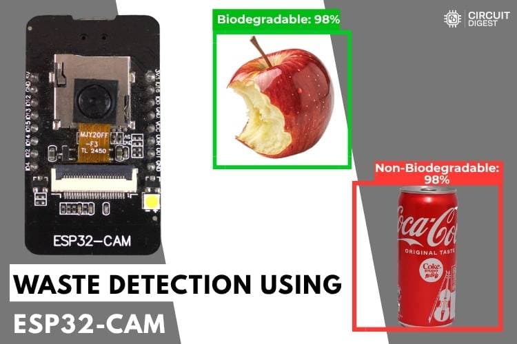
In our day-to-day life, huge amounts of waste are generated in homes, streets, offices, and public places. But the real problem is not just collecting the waste; it is separating it correctly. When biodegradable waste like food waste and leaves gets mixed with non-biodegradable waste like plastic bottles and metal cans, recycling becomes difficult and environmental pollution increases. Manual waste segregation takes time, requires continuous human effort, and often leads to mistakes.
What if a small device could simply look at the waste and decide whether it is in the biodegradable or non-biodegradable category within seconds? That is exactly what this project does. Let's see what it is and how it works. This project solves that problem with a compact, low-cost waste detection system using image processing.
Table of Contents
- How Does the ESP32-CAM Waste Detection System Work?
- Components Required
- Circuit Diagram
- Hardware Connection
- Step-by-Step Procedure
- Code Explanation
- Why Use CircuitDigest Cloud Instead of Training Your Own Model?
- Complete Build & Live Demo
- Advantages and Limitations
- Troubleshooting Common
- GitHub Repository
How Does the ESP32-CAM Waste Detection System Work?
This ESP32-CAM waste detection system module captures an image of the waste with a single button press. Instead of performing all the processing inside the microcontroller, the captured image is transmitted via Wi-Fi to the CircuitDigest Cloud API, where AI-based image analysis is carried out.
The cloud platform processes the image, identifies the type of waste, and sends the classification result back to the ESP32-CAM module. The detected category is then displayed on the serial monitor, indicating whether the waste is biodegradable or non-biodegradable. To provide a clear visual indication, LEDs are used in the system: the red LED glows when biodegradable waste is detected, while the green LED glows for non-biodegradable waste. This makes the system simple, fast, and effective for smart waste segregation applications. We have also built many similar AI projects and ESP32-CAM Projects previously here at CircuitDigest; you can also check them out if you wish to explore more
Components Required for the ESP32 Cam Waste Detection Project
The following table lists every component needed, along with its purpose in the ESP32-CAM waste detection project:
| S.No | Components | Purpose |
| 1. | ESP32-Cam | Used as a microcontroller and also to take photos. |
| 2. | Push Button | Used to give the input by the user to the Microcontroller |
| 3. | Breadboard | Used to make the connections simple and neat. |
| 4. | Red and Green LEDs | Used as an indication for the different kinds of waste |
| 5. | 220 Ohms Resistors | Used for limiting the current |
*Important: If you are using the standard ESP32-CAM (without onboard USB), you will need a USB-to-Serial (FTDI) adapter to program it. Connect FTDI TX → ESP32-CAM RX (U0R), RX → TX (U0T), GND → GND, and hold GPIO0 LOW during upload to enter flash mode. If your board has a micro-USB port already, no adapter is required. If you are just getting started with the ESP32-CAM module, we recommend checking out our guide “How to Program the ESP32-CAM?
Circuit Diagram - ESP32-CAM Waste Detection System
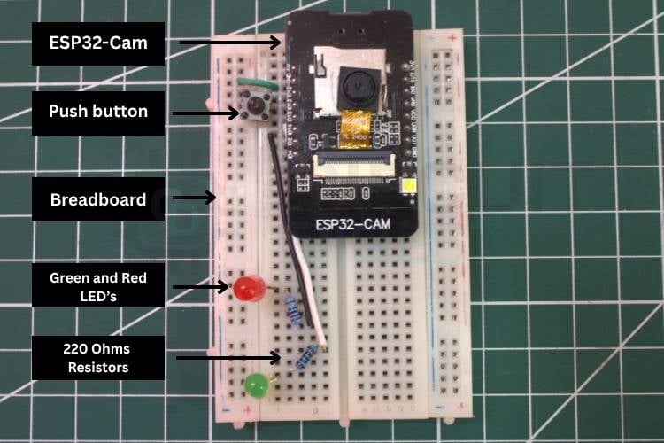
The following circuit diagram shows the connection between the ESP32-CAM, push button, and Breadboard. The push button is connected to GPIO13 of the ESP32-CAM for triggering the photo capture, and the LED’s for indicating the different types of waste.

Hardware Connection Waste Detection System
The image below shows the actual hardware connection, which gives a clear idea of how the components are connected in real life. To power the system, we are using the USB cable connected to the laptop's USB port.
Step-by-Step Procedure to Build the ESP32-CAM Waste Detection System
Let's see a step-by-step procedure for building an object-detection system using the CircuitDigest Cloud waste-detection API.
Step 1⇒Set Up the CircuitDigest Cloud Account
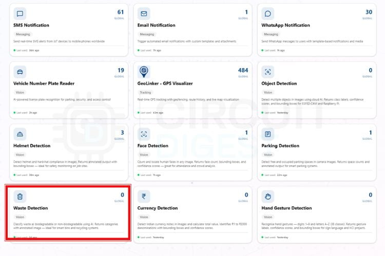
First, you need to make an account on the CircuitDigest Cloud. If you already have one, just go to the CircuitDigest Cloud website, scroll down, find the waste detection feature, click it, and enter.
Step 2⇒Test the API with Sample Images
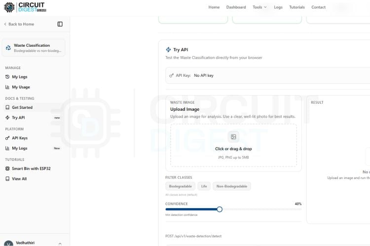
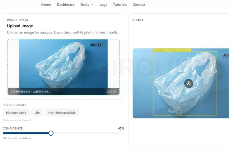
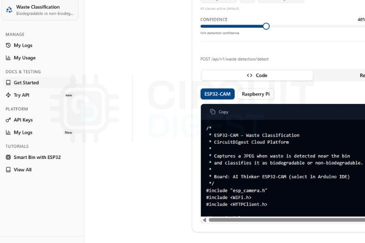
Inside, you’ll notice various options on the left side, such as “Get Started” and “My Usage.” You can also adjust the confidence level based on your requirement, and your API key will be displayed there. Before connecting any hardware, you can test the system using the “Try API” feature. Simply upload an image that contains biodegradable waste and non-biodegradable waste, and click on “Run Test.”
Step 3⇒Review the API Test Results
Within seconds, the system will process the image and display the biodegradable and non-biodegradable waste, as well as life. You can try different images to check the accuracy of detection, but keep in mind that each test consumes your API usage limit, which is restricted to 15 requests per day and 100 per month.
Step 4⇒Assemble the Hardware and Upload the Code
After testing virtually, you can move on to the real-time hardware setup. Connect the ESP32-CAM module according to the circuit diagram and upload the provided code from the ESP32-CAM section. Once the setup is ready, you can either use a sample image or capture a live image of the waste. By pressing the push button connected to GPIO 13, the ESP32-CAM captures an image and immediately sends it to the CircuitDigest waste detection API. The server processes the image and returns the result, which is then displayed on the serial monitor. This entire process, from capturing the image to displaying the biodegradable or non-biodegradable waste within a few seconds.
Step 5⇒ Capture and Classify Waste in Real Time
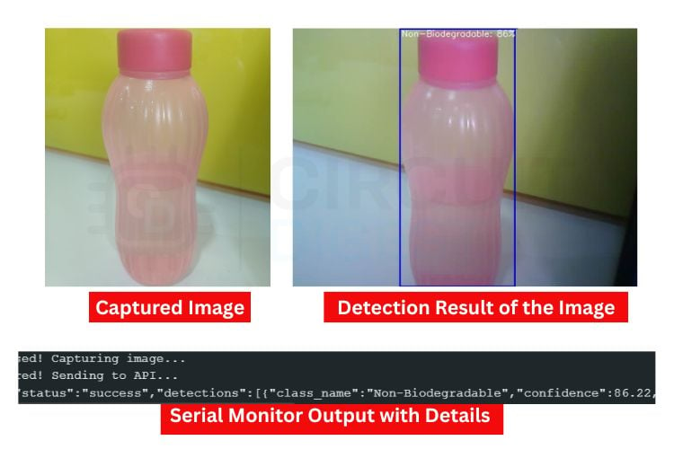
The image below shows the captured image from the ESP32-CAM. Along with it, you can see the detection results of the image. Below that, the Serial Monitor displays the detection output, which indicates whether the waste is biodegradable or non-biodegradable.
Code Explanation of Waste Detection System
In the code, we start by including all the necessary libraries, which include the Wi-Fi-related libraries and the esp_camera camera library. After that, we have defined the WiFi SSID and password along with the CircuitDigest Cloud API key. Make sure these are correct. We have also defined the GPIO pin used with the trigger button.
const char* WIFI_SSID  = "yourssidname";
const char* WIFI_PASS  = "yourwifipassword";
const char* API_KEY    = "yourapikey";
#define TRIGGER_BTN  13
#define GREEN_LED    15
#define RED_LED      14
#define LED_ON_MS    5000
This section contains all the important hardware and network configurations required for the project. The Wi-Fi SSID and password are used to connect the ESP32-CAM to the internet so it can communicate with the CircuitDigest Cloud API. The API key is used for authentication with the cloud server.
void initCamera() {
 camera_config_t cfg = {};
 cfg.pixel_format = PIXFORMAT_JPEG;
 cfg.frame_size   = FRAMESIZE_SVGA;
 cfg.jpeg_quality = 8;
 cfg.fb_count     = 2;
 if (esp_camera_init(&cfg) != ESP_OK) {
   Serial.println("Camera init failed!");
   while (1);
 }
 sensor_t* s = esp_camera_sensor_get();
 s->set_brightness(s, 1);
 s->set_contrast(s, 1);
 s->set_exposure_ctrl(s, 1);
}
This section initializes the ESP32-CAM with the required camera settings. The image format is set to JPEG because it provides good quality while reducing image size for faster cloud upload. The frame size is configured to SVGA for better image clarity.
previewServer.on("/", handleRoot);
previewServer.on("/stream", handleStream);
previewServer.begin();
xTaskCreatePinnedToCore(
 webServerTask,
 "webTask",
 8192,
 NULL,
 1,
 NULL,
 0
);
This section creates a web server inside the ESP32-CAM for live video streaming. When the ESP32 IP address is opened in a browser, the root webpage loads and continuously displays the camera feed through the /stream endpoint.
camera_fb_t* fb = esp_camera_fb_get();
client.println("POST " + String(serverPath) + " HTTP/1.1");
client.println("X-API-Key: " + String(API_KEY));
client.write(imgBuf, imgLen);
String classification =
parseJsonString(json, "classification");
This is the main AI processing section of the project. The ESP32-CAM captures an image frame and sends it securely to the CircuitDigest Cloud API using an HTTPS POST request. The image is uploaded as multipart form data along with the API key for authentication.
The cloud AI analyzes the uploaded waste image and sends back the classification result in JSON format. The ESP32 then extracts important values such as biodegradable count, non-biodegradable count, and overall classification from the response.
if (digitalRead(TRIGGER_BTN) == LOW) {
 unsigned long now = millis();
 if (now - lastTriggerTime > DEBOUNCE_MS) {
   lastTriggerTime = now;
   classifyWaste();
 }
}
flashLed(GREEN_LED);
flashLed(RED_LED);
This section continuously checks whether the push button is pressed. A debounce delay is added to avoid multiple triggers caused by switch bouncing. Once the button is pressed, the ESP32 captures an image and starts the waste classification process. After receiving the AI result, the corresponding LED glows automatically. The green LED indicates biodegradable waste, while the red LED indicates non-biodegradable waste.
Why Use CircuitDigest Cloud Instead of Training Your Own Model?
Platforms like Edge Impulse and TensorFlow Lite require an extensive amount of time for dataset collection, configuring a Machine Learning model and quantisation, as well as deployment. All these processes can take days, even weeks, to complete and require an understanding of Machine Learning. The CircuitDigest Cloud's waste detection service is just a RESTful API with preconfigured and hosted machine learning model(s) being maintained offsite by CircuitDigest. In short, you can get very accurate results simply by making a single HTTPS request.
Here are the key differences between using CircuitDigest Cloud compared to building your own local Machine Learning framework:
∗ Setup time: CircuitDigest Cloud - under 10 minutes; Edge Impulse - several hours to several days.
∗ Hardware Requirements: Any Wi-Fi-enabled MCU; does not require a GPU or high RAM.
∗ Model updates: Completed automatically via the cloud service without having to reflash device firmware.
∗ Cost: Offers a free tier of service (15 requests/day); there are no hardware costs associated with using the service except for the ESP32-CAM.
∗ Accuracy: Continued improvements to models in cloud vs static models once deployed as an on-device TFLite model.
Smart Waste Detection Powered by ESP32-CAM: Complete Build & Live Demo
Watch the complete build and live demonstration of the ESP32-CAM waste detection system in the video below:
Advantages and Limitations of the ESP32-CAM Waste Detection System
The table below summarises the key strengths and constraints of this ESP32-CAM waste detection project to help you evaluate its suitability for your application:
| S.No | Advantages | Limitations |
| 1. | Real-time waste detection within a few seconds | Cannot work without cloud API access |
| 2. | Low-cost system using ESP32-CAM with built-in camera and Wi-Fi | Requires an internet connection for waste detection |
| 3. | No need for expensive hardware or powerful processors | Blurry images may give wrong results |
| 4. | Wireless communication without extra modules | Limited by daily or monthly API usage limits |
| 5. | Small size and portable design | Only captures single images, not fully live video detection |
Troubleshooting Common Issues in the Waste Detection System
Issue 1: Memory Allocation Failure (Capture Failed)
If the system displays “Camera capture failed,” it may be due to insufficient memory allocation in the frame buffer. High-resolution images consume more PSRAM, and if memory is not available, capture will fail. Reducing frame size, lowering JPEG quality, or ensuring that PSRAM is properly enabled in the board configuration can help resolve this issue.
Issue 2: ESP32-CAM Restarting Automatically
The ESP32-CAM restarting is one of the common issues. Sometimes the power is received by the USB port of the laptop, so if it's restarting again and again, try with the external power source. Also, ensure the connection is made properly.
Issue 3: Blurry or Low-Quality Images
If the captured images appear blurry or unclear, it may be due to improper focus or lighting conditions. The ESP32-CAM lens is adjustable, so manually rotating the lens can improve focus. Additionally, ensure that the environment has sufficient lighting, as low light can introduce noise and reduce detection accuracy. Adjusting camera parameters such as brightness and contrast can also improve image quality.
Issue 4: Camera Initialisation Failed
If the ESP32-CAM fails to initialise the camera, it is usually due to incorrect pin configuration, insufficient power supply, or improper board selection in the IDE. Ensure that the correct camera model, which is AI Thinker ESP32-Cam, is selected and that all the GPIOs given match the hardware configuration.
Issue 5: No Detection or Incorrect Results
If the system fails to detect objects or produces inaccurate results, it is often due to poor image quality, improper lighting, or unsuitable confidence threshold settings. Ensure that the camera is placed in a well-lit environment and properly focused on the target object. Adjusting parameters such as brightness, contrast, and confidence threshold can significantly improve detection accuracy.
One of the key reasons for choosing this platform over alternatives such as Edge Impulse or other machine learning training frameworks is simplicity and accessibility. Platforms like Edge Impulse typically require dataset collection, model training, optimization, and deployment, which can be time-consuming and complex, especially for beginners. But CircuitDigest Cloud provides a ready-to-use API that eliminates the need for model training, enabling faster development and immediate results. We have also done an AI-Powered Autonomous Waste-Collecting and Sorting Robot that collects and sorts waste; go through the project for more details.
ESP32 Cam Waste Detection GitHub
This GitHub project demonstrates a smart waste detection and monitoring system using ESP32-CAM and computer vision to identify waste objects in real time. Designed for IoT and environmental automation applications, the system can help enable smart bins, automated waste detection, and intelligent monitoring solutions using low-cost embedded hardware.


Frequently Asked Questions - ESP32-CAM Waste Detection System
⇥ Why is the cloud API used instead of local processing?
The ESP32-CAM has limited memory and processing power, which makes it difficult to run complex AI models locally. The cloud API performs heavy image processing on powerful servers, providing better accuracy and faster waste classification results.
⇥ What happens when the push button is pressed?
When the push button is pressed, the ESP32-CAM captures an image of the waste and sends it to the CircuitDigest Cloud API. The server processes the image and classifies it as biodegradable or non-biodegradable waste.
⇥ Can this system detect multiple waste types at the same time?
Yes, if multiple waste objects are visible in the image, the system can analyse them and identify different waste categories depending on the API model and supported classes.
⇥ Can this system work without an internet connection?
No, the system requires an active internet connection because the waste detection and classification are performed on the cloud server.
⇥ How can detection accuracy be improved?
Detection accuracy can be improved by ensuring proper lighting, clear image quality, correct camera angle, and adjusting the confidence threshold in the API settings.
Related CircuitDigest Cloud Projects
Explore related CircuitDigest Cloud projects that demonstrate how to send real-time email notifications using ESP32, Arduino, and Raspberry Pi Pico. These projects showcase practical IoT applications for alerts, monitoring, and automation using cloud connectivity and embedded systems.
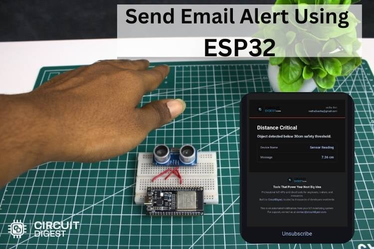
How to send an email from ESP32 for sensor monitoring and status updates
In this tutorial, we will learn how to send an email from your ESP32 microcontroller. This feature allows important details such as sensor data, time of occurrence, images, and system status to be sent through email in a clear and reliable format.
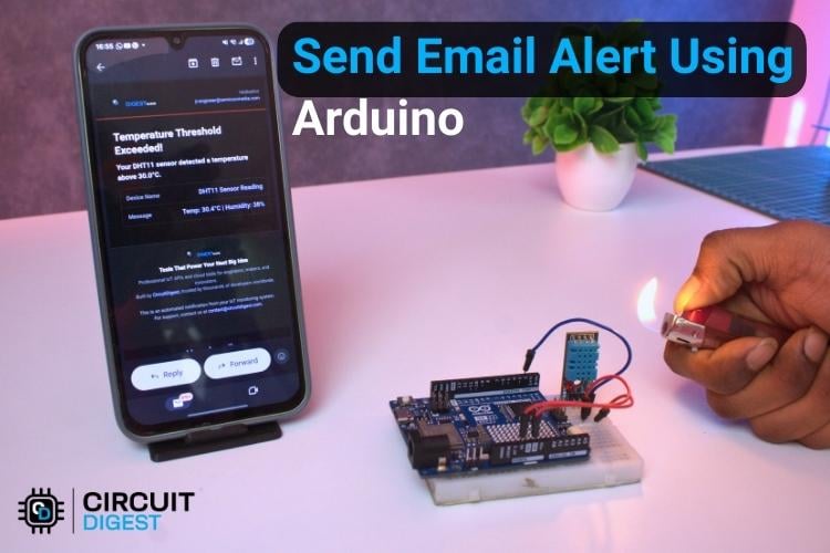
How to Send Email Notifications from Arduino using CircuitDigest Cloud
In this project, we will show you exactly how to send an email alert using Arduino paired with a DHT11 temperature and humidity sensor. The DHT11 monitors the environment continuously, and when readings exceed your preset limits
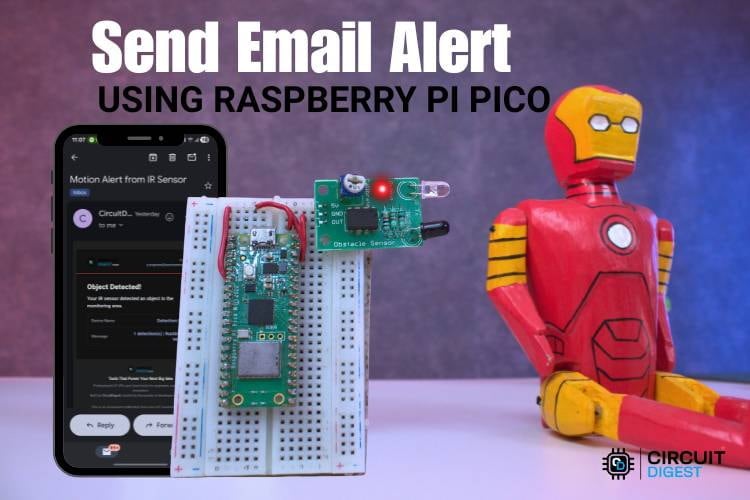
How to Send Email Notifications from Raspberry Pi Pico using CircuitDigest Cloud
In this project, the Raspberry Pi Pico W connects to WiFi and sends an automatic email notification when a trigger event happens. You will also find full code references and links to the Raspberry Pi Pico W email alert GitHub repository for implementation.
Complete Project Code
#include "esp_camera.h"
#include <WiFi.h>
#include <WiFiClientSecure.h>
#include <WebServer.h>
// ── Wi-Fi & API ────────────────────────────────────────────────────────────
const char* WIFI_SSID  = "yourssidname";
const char* WIFI_PASS  = "yourwifipassword";
const char* API_KEY    = "yourapikey";
const char* serverName = "www.circuitdigest.cloud";
const char* serverPath = "/api/v1/waste-detection/detect";
const int   serverPort = 443;
// ── Button ─────────────────────────────────────────────────────────────────
#define TRIGGER_BTN  13
#define DEBOUNCE_MS  500
// ── LEDs ───────────────────────────────────────────────────────────────────
#define GREEN_LED    15   // GPIO 15 — glows for biodegradable waste
#define RED_LED      14   // GPIO 14 — glows for non-biodegradable waste
#define LED_ON_MS    5000 // how long the LED stays on (5 seconds)
// ── AI Thinker pin map ─────────────────────────────────────────────────────
#define PWDN_GPIO_NUM  32
#define RESET_GPIO_NUM -1
#define XCLK_GPIO_NUM   0
#define SIOD_GPIO_NUM  26
#define SIOC_GPIO_NUM  27
#define Y9_GPIO_NUM    35
#define Y8_GPIO_NUM    34
#define Y7_GPIO_NUM    39
#define Y6_GPIO_NUM    36
#define Y5_GPIO_NUM    21
#define Y4_GPIO_NUM    19
#define Y3_GPIO_NUM    18
#define Y2_GPIO_NUM     5
#define VSYNC_GPIO_NUM 25
#define HREF_GPIO_NUM  23
#define PCLK_GPIO_NUM  22
WiFiClientSecure client;
WebServer previewServer(80);
SemaphoreHandle_t camMutex    = NULL;
unsigned long lastTriggerTime = 0;
// ── Camera lock helpers ────────────────────────────────────────────────────
inline bool lockCam(TickType_t wait = portMAX_DELAY) {
 return xSemaphoreTake(camMutex, wait) == pdTRUE;
}
inline void unlockCam() { xSemaphoreGive(camMutex); }
// ── LED helper: flash one LED for LED_ON_MS then turn it off ───────────────
// Non-blocking: spawns a one-shot FreeRTOS task so loop() isn't stalled.
struct LedJob { uint8_t pin; uint32_t ms; };
void ledTask(void* arg) {
 LedJob* job = (LedJob*)arg;
 digitalWrite(job->pin, HIGH);
 vTaskDelay(pdMS_TO_TICKS(job->ms));
 digitalWrite(job->pin, LOW);
 delete job;
 vTaskDelete(NULL);   // self-delete
}
void flashLed(uint8_t pin, uint32_t ms = LED_ON_MS) {
 // Make sure the other LED is off first
 digitalWrite((pin == GREEN_LED) ? RED_LED : GREEN_LED, LOW);
 LedJob* job = new LedJob{pin, ms};
 xTaskCreate(ledTask, "led", 1024, job, 2, NULL);
}
// ── Camera init ────────────────────────────────────────────────────────────
void initCamera() {
 camera_config_t cfg = {};
 cfg.ledc_channel = LEDC_CHANNEL_0; cfg.ledc_timer = LEDC_TIMER_0;
 cfg.pin_d0 = Y2_GPIO_NUM;  cfg.pin_d1 = Y3_GPIO_NUM;
 cfg.pin_d2 = Y4_GPIO_NUM;  cfg.pin_d3 = Y5_GPIO_NUM;
 cfg.pin_d4 = Y6_GPIO_NUM;  cfg.pin_d5 = Y7_GPIO_NUM;
 cfg.pin_d6 = Y8_GPIO_NUM;  cfg.pin_d7 = Y9_GPIO_NUM;
 cfg.pin_xclk     = XCLK_GPIO_NUM;   cfg.pin_pclk     = PCLK_GPIO_NUM;
 cfg.pin_vsync    = VSYNC_GPIO_NUM;  cfg.pin_href     = HREF_GPIO_NUM;
 cfg.pin_sscb_sda = SIOD_GPIO_NUM;   cfg.pin_sscb_scl = SIOC_GPIO_NUM;
 cfg.pin_pwdn     = PWDN_GPIO_NUM;   cfg.pin_reset    = RESET_GPIO_NUM;
 cfg.xclk_freq_hz = 20000000;
 cfg.pixel_format = PIXFORMAT_JPEG;
 cfg.frame_size   = FRAMESIZE_SVGA;  // 800x600 for smooth preview
 cfg.jpeg_quality = 8;
 cfg.fb_count     = 2;
 if (esp_camera_init(&cfg) != ESP_OK) {
   Serial.println("Camera init failed!"); while (1);
 }
 sensor_t* s = esp_camera_sensor_get();
 s->set_brightness(s, 1);
 s->set_contrast(s, 1);
 s->set_saturation(s, 0);
 s->set_whitebal(s, 1);
 s->set_exposure_ctrl(s, 1);
 s->set_gain_ctrl(s, 1);
 s->set_aec2(s, 1);
 s->set_ae_level(s, 1);
 Serial.println("Camera initialized.");
}
// ── WiFi reconnect helper ──────────────────────────────────────────────────
bool ensureWiFi() {
 if (WiFi.status() == WL_CONNECTED) return true;
 Serial.print("WiFi lost, reconnecting");
 WiFi.begin(WIFI_SSID, WIFI_PASS);
 for (int i = 0; i < 20 && WiFi.status() != WL_CONNECTED; i++) {
   delay(500); Serial.print(".");
 }
 if (WiFi.status() == WL_CONNECTED) {
   Serial.println(" OK: " + WiFi.localIP().toString());
   return true;
 }
 Serial.println(" FAILED");
 return false;
}
// ── JSON string parser ─────────────────────────────────────────────────────
String parseJsonString(const String& json, const String& key) {
 int idx = json.indexOf("\"" + key + "\":");
 if (idx == -1) return "";
 int start = json.indexOf('"', idx + key.length() + 3);
 if (start == -1) return "";
 start++;
 int end = json.indexOf('"', start);
 if (end == -1) return "";
 return json.substring(start, end);
}
// ── JSON int parser ────────────────────────────────────────────────────────
int parseJsonInt(const String& json, const String& key) {
 int idx = json.indexOf("\"" + key + "\":");
 if (idx == -1) return -1;
 int start = idx + key.length() + 3;
 while (start < (int)json.length() && !isDigit(json[start])) start++;
 int end = start;
 while (end < (int)json.length() && isDigit(json[end])) end++;
 if (end == start) return -1;
 return json.substring(start, end).toInt();
}
// ── Web preview handlers ───────────────────────────────────────────────────
void handleRoot() {
 previewServer.send(200, "text/html",
   "<!DOCTYPE html><html><head>"
   "<meta name='viewport' content='width=device-width,initial-scale=1'>"
   "<style>"
   "body{background:#111;margin:0;display:flex;flex-direction:column;"
   "align-items:center;justify-content:center;min-height:100vh;font-family:sans-serif}"
   "h2{color:#fff;margin:12px 0 4px}p{color:#aaa;margin:0 0 12px;font-size:13px}"
   "img{width:100%;max-width:640px;border:1px solid #333;border-radius:6px}"
   "</style>"
   "<script>"
   "var retries=0;"
   "function reloadStream(){"
   "  retries++;"
   "  var delay=Math.min(500*retries,5000);"
   "  var img=document.getElementById('s');"
   "  setTimeout(function(){img.src='/stream?t='+Date.now();},delay);"
   "}"
   "</script>"
   "</head><body>"
   "<h2>Waste Classification Preview</h2>"
   "<p>Press the button to classify waste</p>"
   "<img id='s' src='/stream' onerror='reloadStream()'>"
   "</body></html>"
 );
}
void handleStream() {
 WiFiClient streamClient = previewServer.client();
 streamClient.println("HTTP/1.1 200 OK");
 streamClient.println("Content-Type: multipart/x-mixed-replace; boundary=frame");
 streamClient.println("Cache-Control: no-cache");
 streamClient.println("Connection: close");
 streamClient.println();
 const TickType_t lockWait = pdMS_TO_TICKS(200);
 const uint32_t   frameGap = 50;
 const uint32_t   yieldGap = 80;
 const uint32_t   watchdog = 8000;
 uint32_t lastFrame = millis();
 while (streamClient.connected()) {
   if (millis() - lastFrame > watchdog) {
     Serial.println("[stream] watchdog timeout");
     break;
   }
   if (!lockCam(lockWait)) {
     vTaskDelay(pdMS_TO_TICKS(yieldGap));
     continue;
   }
   camera_fb_t* discard = esp_camera_fb_get();
   if (discard) esp_camera_fb_return(discard);
   camera_fb_t* fb = esp_camera_fb_get();
   unlockCam();
   if (!fb) { vTaskDelay(pdMS_TO_TICKS(10)); continue; }
   streamClient.print("--frame\r\nContent-Type: image/jpeg\r\nContent-Length: ");
   streamClient.print(fb->len);
   streamClient.print("\r\n\r\n");
   size_t written = streamClient.write(fb->buf, fb->len);
   streamClient.print("\r\n");
   esp_camera_fb_return(fb);
   if (written == 0) { Serial.println("[stream] write failed"); break; }
   lastFrame = millis();
   vTaskDelay(pdMS_TO_TICKS(frameGap));
 }
 streamClient.stop();
 Serial.println("[stream] client disconnected");
}
void webServerTask(void* param) {
 while (true) {
   previewServer.handleClient();
   vTaskDelay(1);
 }
}
// ── Waste classification ───────────────────────────────────────────────────
void classifyWaste() {
 if (!ensureWiFi()) return;
 if (!lockCam(pdMS_TO_TICKS(3000))) {
   Serial.println("Could not lock camera — try again");
   return;
 }
 sensor_t* s = esp_camera_sensor_get();
 s->set_framesize(s, FRAMESIZE_VGA);
 s->set_quality(s, 10);
 delay(150);
 camera_fb_t* warmup = esp_camera_fb_get();
 if (warmup) esp_camera_fb_return(warmup);
 delay(200);
 camera_fb_t* fb = esp_camera_fb_get();
 if (!fb) {
   Serial.println("Capture failed");
   s->set_framesize(s, FRAMESIZE_SVGA);
   s->set_quality(s, 8);
   unlockCam();
   return;
 }
 Serial.printf("Captured %u bytes\n", fb->len);
 s->set_framesize(s, FRAMESIZE_SVGA);
 s->set_quality(s, 8);
 size_t   imgLen = fb->len;
 uint8_t* imgBuf = (uint8_t*)malloc(imgLen);
 if (!imgBuf) {
   Serial.println("malloc failed");
   esp_camera_fb_return(fb);
   unlockCam();
   return;
 }
 memcpy(imgBuf, fb->buf, imgLen);
 esp_camera_fb_return(fb);
 unlockCam();
 // ── HTTPS upload ───────────────────────────────────────────────────────
 Serial.println("Sending to API...");
 if (!client.connect(serverName, serverPort)) {
   Serial.println("Connection to API server failed");
   free(imgBuf);
   return;
 }
 String boundary   = "----ESP32Boundary";
 String head       = "--" + boundary + "\r\n"
                     "Content-Disposition: form-data; name=\"imageFile\"; filename=\"snap.jpg\"\r\n"
                     "Content-Type: image/jpeg\r\n\r\n";
 String tail       = "\r\n--" + boundary + "--\r\n";
 int    contentLen = head.length() + (int)imgLen + tail.length();
 client.println("POST " + String(serverPath) + " HTTP/1.1");
 client.println("Host: " + String(serverName));
 client.println("X-API-Key: " + String(API_KEY));
 client.println("Content-Type: multipart/form-data; boundary=" + boundary);
 client.println("Content-Length: " + String(contentLen));
 client.println("Connection: close");
 client.println();
 client.print(head);
 client.write(imgBuf, imgLen);
 client.print(tail);
 free(imgBuf);
 // ── Read response ──────────────────────────────────────────────────────
 uint32_t t = millis();
 while (!client.available()) {
   if (millis() - t > 15000) {
     Serial.println("API timeout"); client.stop(); return;
   }
   delay(10);
 }
 String response = "";
 while (client.available()) response += (char)client.read();
 client.stop();
 int jsonStart = response.indexOf("\r\n\r\n");
 String json = (jsonStart != -1) ? response.substring(jsonStart + 4) : response;
 Serial.println("Response: " + json);
 // ── Parse result ───────────────────────────────────────────────────────
 String classification = parseJsonString(json, "classification");
 int    bioCount       = parseJsonInt(json, "biodegradable");
 int    nonBioCount    = parseJsonInt(json, "non_biodegradable");
 Serial.println("=== WASTE DETECTION RESULT ===");
 if (classification.length() > 0) {
   Serial.println("Classification      : " + classification);
 }
 if (bioCount >= 0) {
   Serial.println("Biodegradable items : " + String(bioCount));
 }
 if (nonBioCount >= 0) {
   Serial.println("Non-biodegradable   : " + String(nonBioCount));
 }
 // ── LED indication ─────────────────────────────────────────────────────
 // Priority logic:
 //   • If classification string contains "non" → red LED
 //   • Else if it contains "bio" / "organic" → green LED
 //   • Fallback: compare counts — whichever is higher wins
 //   • If both counts are equal and > 0 → both flash red (mixed waste)
 String cls = classification;
 cls.toLowerCase();
 if (cls.indexOf("non") != -1) {
   // Explicitly non-biodegradable
   Serial.println("LED: RED (non-biodegradable)");
   flashLed(RED_LED);
 } else if (cls.indexOf("bio") != -1 || cls.indexOf("organic") != -1) {
   // Explicitly biodegradable / organic
   Serial.println("LED: GREEN (biodegradable)");
   flashLed(GREEN_LED);
 } else if (bioCount >= 0 && nonBioCount >= 0) {
   // No clear string — use counts
   if (nonBioCount > bioCount) {
     Serial.println("LED: RED (more non-biodegradable items)");
     flashLed(RED_LED);
   } else if (bioCount > nonBioCount) {
     Serial.println("LED: GREEN (more biodegradable items)");
     flashLed(GREEN_LED);
   } else if (bioCount > 0) {
     // Equal non-zero — mixed waste, flash red as warning
     Serial.println("LED: RED (mixed waste)");
     flashLed(RED_LED);
   } else {
     Serial.println("LED: none (no waste detected)");
   }
 } else {
   Serial.println("Could not determine waste type — no LED triggered");
 }
 Serial.println("==============================");
}
// ── Setup ──────────────────────────────────────────────────────────────────
void setup() {
 Serial.begin(115200);
 // LEDs
 pinMode(GREEN_LED, OUTPUT);
 pinMode(RED_LED,   OUTPUT);
 digitalWrite(GREEN_LED, LOW);
 digitalWrite(RED_LED,   LOW);
 pinMode(TRIGGER_BTN, INPUT_PULLUP);
 camMutex = xSemaphoreCreateMutex();
 initCamera();
 client.setInsecure();
 WiFi.begin(WIFI_SSID, WIFI_PASS);
 Serial.print("Connecting to WiFi");
 while (WiFi.status() != WL_CONNECTED) { delay(500); Serial.print("."); }
 Serial.println("\nConnected: " + WiFi.localIP().toString());
 Serial.println("Preview:   http://" + WiFi.localIP().toString());
 previewServer.on("/",       handleRoot);
 previewServer.on("/stream", handleStream);
 previewServer.begin();
 xTaskCreatePinnedToCore(webServerTask, "webTask", 8192, NULL, 1, NULL, 0);
 Serial.println("Ready — press button to classify waste");
}
// ── Loop (Core 1) ──────────────────────────────────────────────────────────
void loop() {
 if (digitalRead(TRIGGER_BTN) == LOW) {
   unsigned long now = millis();
   if (now - lastTriggerTime > DEBOUNCE_MS) {
     lastTriggerTime = now;
     Serial.println("Button pressed — capturing...");
     classifyWaste();
   }
 }
}

Add a comment
No account needed. Your comment appears once a moderator has reviewed it.