
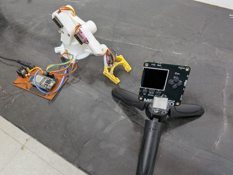
This project aims to develop an intelligent robot that can automatically collect and sort waste using artificial intelligence and camera-based sensing. The robot utilizes the Adafruit Memento Camera powered by the ESP32-S3 microcontroller as the main vision and processing unit. The camera captures images of waste materials and runs an on-device AI model to detect and identify different types of waste such as dry, wet, and metal. Once the waste type is identified, the ESP32-S3 does not directly control the motors. Instead, it communicates the classification result to a separate ESP32 NodeMCU board that is responsible for actuation and robotic movement.
The communication between the ESP32-S3 and the ESP32 NodeMCU is achieved using ESP-NOW protocol, which allows device-to-device communication without internet connectivity. The ESP32-S3 acts as the transmitter and sends the waste category data directly to the NodeMCU using the specific MAC address of the receiver board. The NodeMCU acts as the receiver and is programmed with its unique MAC ID. Since the communication happens using predefined MAC addresses, no Wi-Fi router or internet connection is required, making the system fast, secure, and fully offline.
The ESP32 NodeMCU is connected to multiple servo motors that form a robotic hand mechanism. When the NodeMCU receives the category instruction (for example: wet, dry, or metal), it activates the corresponding servo movement sequence. The robotic hand picks up the waste object, rotates to the appropriate bin location, and places it into the designated compartment. This separation of processing and actuation ensures stable AI performance and reliable motor control.
Overall, this system demonstrates how artificial intelligence, embedded systems, wireless communication, and robotics can be integrated to create a fully automated waste segregation robot. The system operates without internet dependency, using direct MAC-based communication between microcontrollers, making it efficient, low-latency, and suitable for smart waste management applications.
Components Required
Component Name | Quantity | Datasheet/Link |
| MOMENTO Programmable Camera from Adafruit | 1 | - |
| ESP32 30 Pin Node MCU | 1 | - |
| MG 90 S | 4 | - |
| 18650 Rechargeable Li-Ion Battery | 3 | - |
Circuit Diagram
The circuit consists of two main processing units: the Adafruit Memento (ESP32-S3) module for AI-based image processing and an ESP32 NodeMCU board for robotic arm control. The power system is designed using a 12V battery source, which is stepped down to 5V using a buck converter module to safely power the servos and controller boards.

Power Section
A 12V battery pack supplies the system. The voltage is reduced to 5V using a step-down buck converter. This regulated 5V output powers:
The servo motors
The ESP32 NodeMCU
The Adafruit Memento module (via Vcc and GND connections)
All grounds (GND) are connected together to maintain a common reference.
Servo Motor Connections
Four MG90S servo motors (S1, S2, S3, S4) are connected to the ESP32 NodeMCU.
Each servo has:
Red wire → 5V from buck converter
Brown/Black wire → GND
Signal wire → Individual GPIO pins of ESP32
The ESP32 controls these servos to operate the robotic hand for picking and placing waste into different bins.
Adafruit Memento (ESP32-S3) Module
The Memento module acts as the vision and AI processing unit. It includes:
ESP32-S3 processor
Integrated camera module
Wi-Fi and Bluetooth capability
The camera captures images of the waste object. The onboard AI model processes the image and classifies the waste type (wet, dry, or metal). This processing happens directly on the ESP32-S3 using edge computing.
The Memento is powered through 5V and GND connections from the regulated power supply.
Wireless Communication Between Memento and ESP32
The Adafruit Memento (ESP32-S3) and the ESP32 NodeMCU communicate wirelessly using the ESP-NOW protocol.
How Communication Works
The ESP32-S3 (Memento) acts as the Transmitter
The ESP32 NodeMCU acts as the Receiver
Communication occurs using each device’s unique MAC address
No internet or router is required
MAC ID-Based Communication
Each ESP32 board has a unique MAC address (for example: 24:6F:28:AA:BB:CC).
In the program:
The ESP32-S3 stores the MAC address of the NodeMCU.
When waste is classified, the ESP32-S3 sends a small data packet (like 1 = wet, 2 = dry, 3 = metal).
Only the ESP32 with the matching MAC ID receives the data.
This makes the system:
Fast
Secure
Independent of internet
Low latency
Suitable for real-time robotic control
Hardware Assembly
System Flow Explanation (With Pin Numbers)
Power Initialization
12V Battery → Buck ConverterBuck Converter Output (5V) →
ESP32 NodeMCU (VIN / 5V pin)
Adafruit Memento (5V pin)
Servo motors (Red wire)
All GND connections are connected together (Common Ground).
Object Placement
Waste is placed in front of the Adafruit Memento (ESP32-S3) camera.
Image Capture (Memento ESP32-S3)
Camera is built-in to the Memento module.
AI processing runs inside ESP32-S3.
No external GPIO used for camera (internally connected).
AI Classification
The ESP32-S3 processes the image and identifies:
Wet
Dry
Metal
Wireless Transmission (ESP-NOW)
ESP32-S3 acts as Transmitter
ESP32 NodeMCU acts as Receiver
Communication uses NodeMCU’s MAC address
No internet required
Data format example:
1 → Wet
2 → Dry
3 → Metal
ESP32 NodeMCU Pin Connections (Robotic Arm)
Servo connections:
ServoESP32 PinBase ServoGPIO 13Shoulder ServoGPIO 12Elbow ServoGPIO 14Gripper ServoGPIO 27
Servo Wiring:
Red → 5V (Buck converter)
Brown/Black → GND
Yellow/Orange → ESP32 GPIO (13,12,14,27)
Servo Action Flow
When NodeMCU receives data:
If 1 (Wet) → Rotate base to Wet bin position
If 2 (Dry) → Rotate to Dry bin
If 3 (Metal) → Rotate to Metal bin
Servo movement sequence:
Open gripper
Lower arm
Close gripper
Lift arm
Rotate base
Release waste
System Reset
After placing the waste:
Arm returns to initial position
System waits for next object
Important Electrical Notes
Servos are powered from external 5V
ESP32 logic operates at 3.3V
All grounds must be common
Memento and NodeMCU communicate wirelessly using MAC ID
Code Explanation
MEMENTO CODE (ESP32-S3)
#include <WiFi.h>
#include <esp_now.h>
// Replace with your NodeMCU MAC address
uint8_t receiverMAC[] = {0x24, 0x6F, 0x28, 0xAA, 0xBB, 0xCC};
typedef struct {
int wasteType;  // 1=Wet, 2=Dry, 3=Metal
} MessageData;
MessageData data;
void setup() {
Serial.begin(115200);
WiFi.mode(WIFI_STA);
if (esp_now_init() != ESP_OK) {
 Serial.println("ESP-NOW Init Failed");
 return;
}
esp_now_peer_info_t peerInfo = {};
memcpy(peerInfo.peer_addr, receiverMAC, 6);
peerInfo.channel = 0;
peerInfo.encrypt = false;
esp_now_add_peer(&peerInfo);
Serial.println("Transmitter Ready");
}
void loop() {
int aiResult = 1;
data.wasteType = aiResult;
esp_now_send(receiverMAC, (uint8_t *) &data, sizeof(data));
Serial.print("Sent Waste Type: ");
Serial.println(aiResult);
delay(3000);
}
NODEMCU CODE (Receiver)
#include <WiFi.h>
#include <esp_now.h>
#include <Servo.h>
// Servo pins
#define BASE_SERVO 13
#define SHOULDER_SERVO 12
#define ELBOW_SERVO 14
#define GRIPPER_SERVO 27
Servo baseServo, shoulderServo, elbowServo, gripperServo;
typedef struct {
int wasteType;
} MessageData;
MessageData receivedData;
void onReceive(const uint8_t * mac, const uint8_t *incomingData, int len) {
memcpy(&receivedData, incomingData, sizeof(receivedData));
Serial.print("Received Waste Type: ");
Serial.println(receivedData.wasteType);
if (receivedData.wasteType == 1) moveToWet();
else if (receivedData.wasteType == 2) moveToDry();
else if (receivedData.wasteType == 3) moveToMetal();
}
void setup() {
Serial.begin(115200);
WiFi.mode(WIFI_STA);
Serial.print("Receiver MAC: ");
Serial.println(WiFi.macAddress());
if (esp_now_init() != ESP_OK) {
 Serial.println("ESP-NOW Init Failed");
 return;
}
esp_now_register_recv_cb(onReceive);
baseServo.attach(BASE_SERVO);
shoulderServo.attach(SHOULDER_SERVO);
elbowServo.attach(ELBOW_SERVO);
gripperServo.attach(GRIPPER_SERVO);
Serial.println("Receiver Ready");
}
void loop() {
// Nothing here, everything handled in onReceive()
}
//  Movement Functions
void pickObject() {
gripperServo.write(30);  // Open
delay(500);
shoulderServo.write(60); // Lower arm
delay(1000);
gripperServo.write(80);  // Close
delay(500);
shoulderServo.write(20); // Lift
delay(1000);
}
void moveToWet() {
pickObject();
baseServo.write(30);  // Wet bin position
delay(1000);
gripperServo.write(30); // Release
}
void moveToDry() {
pickObject();
baseServo.write(90);  // Dry bin
delay(1000);
gripperServo.write(30);
}
void moveToMetal() {
pickObject();
baseServo.write(150); // Metal bin
delay(1000);
gripperServo.write(30);
}