 Vedhathiri
Author
Fossil fuels have been consumed rapidly over recent decades, and their availability is decreasing. Because of this, there is a growing focus on renewable energy sources. Solar energy is one of the most reliable options since sunlight is available throughout the day. Solar panels absorb solar radiation and transform it into electrical energy. The intensity and angle at which sunlight strikes the panels determine how much energy is produced.
Conventional solar panels cannot completely utilise sunlight throughout the day since they are stuck in one location. For that, we first created a Single-Axis Solar Tracker, which monitors the sun's location along a single axis, but to maximise energy efficiency, we used dual axis solar tracking system using Arduino that enables the solar panel to change in both horizontal and vertical directions based on the sun's location. This Arduino dual axis solar tracker project using LDR and servo motors, can increase energy output by up to 40% compared to fixed solar installations. If you are interested in more project ideas in the area of Arduino, our site is there to help you with it. Do check our Arduino Projects and Tutorials.
Table of Contents
- What is a Dual Axis Solar Tracker System?
- Components Required
- Circuit Diagram
- └ Key Circuit Features
- └ Pin Configuration Table
- Assembly Process
- Arduino Code Explanation
- Working Principle
- └ Tracking Algorithm Workflow
- Real-Time Tracking Demonstration
- Comparison of Dual Axis Solar Tracker Over Fixed Systems
- GitHub Repository
What is a Dual Axis Solar Tracker System?
A dual axis solar tracker system, or adjustable solar panel, is an automated system that adjusts the orientation of a solar panel along two axes of rotation, azimuth (horizontal) and elevation (vertical), allowing it to follow the sun's position during daylight hours. An arduino dual axis solar tracker uses light-dependent resistors (LDRs) to measure sunlight intensity and servo motors to physically adjust the solar panel angle so that the solar panel captures maximum sunlight from sunrise to sunset.
Components Required for Arduino Dual Axis Solar Tracker Project
Building an Arduino dual axis solar tracker project using ldr and servo motors requires specific electronic and mechanical components. Here, we’ll quickly look at each component needed to assemble the dual axis solar power tracker system.
Hardware Components
| Components | Quantity | Purpose in Dual Axis Solar Tracker |
| Arduino UNO | 1 | Main controller for the tracking system |
| LDR(5mm) | 4 | Light-dependent resistors detect sunlight direction |
| Solar Panel | 1 | Captures solar energy |
| Micro-Servo Motor | 2 | Controls horizontal and vertical axis movement |
| 10k ohms Resistor | 4 | Forms voltage divider circuit with LDRs |
| Breadboard | 1 | Circuit prototyping and connections |
| Jumper cables | Required amount | Electrical connections between components |
The figure above shows the Essential components for building a dual axis solar tracking system using Arduino
Software Requirements
Arduino IDE
Dual Axis Solar Tracking System Circuit Diagram
Let’s dive into the circuit connections of the dual axis solar tracker system. Understanding the wiring is crucial for the successful implementation of this Arduino dual axis solar tracker project.
![]()
Circuit Connection Details
The circuit architecture of this dual axis solar power tracker system is built around an Arduino UNO microcontroller that orchestrates two servo motors for horizontal (azimuth) and vertical (elevation) rotation. Four LDR sensors are arranged in a cross formation to detect light intensity from the top, bottom, left, and right. Each LDR is paired with a 10kΩ resistor to form a voltage divider, enabling accurate analog readings. Based on the light detected by each sensor, the Arduino calculates where the sunlight is strongest and adjusts the servos accordingly. This keeps the panel aligned with the brightest point throughout the day, making it an efficient dual axis solar power tracker system.
Key Circuit Features of the Arduino Dual Axis Solar Tracker
- LDR Placement: cross-configuration to help detect light from any angle.
- Voltage Divider Network Resistors: 10kΩ resistors with each LDR provide meaningful readings.
- Servo Controls are Separate: servo motors controlling the X-axis and Y-axis are controlled separately.
- Analog Input Pins: analog input channels A0-A3 are used for LDR sensor readings.
![]()
The above image shows the real-time circuit connection made for the Dual Axis Solar Tracking System.
Pin Configuration Table for Arduino Dual Axis Solar Tracker
| Component | Arduino Pin | Function |
| LDR Top-Left | A0 | Upper-left light detection |
| LDR Top-Right | A3 | Upper-right light detection |
| LDR Bottom-Left | A1 | Lower-left light detection |
| LDR Bottom-Right | A2 | Lower-right light detection |
| Horizontal Servo | Digital Pin 2 | Controls left-right movement |
| Vertical Servo | Digital Pin 13 | Controls up-down movement |
Assembly Process for Dual Axis Solar Tracker System
All mechanical components used to assemble the arduino dual axis solar tracker were 3D-printed, ensuring precise alignment and stable movement. The 3D models referenced in this project were sourced from the article published at:
https://simplecircuitslol.blogspot.com/2024/12/solar-tracking-system.html
![]()
The above image illustrates the 3D model of the components utilised in the dual axis solar tracking system using Arduino.
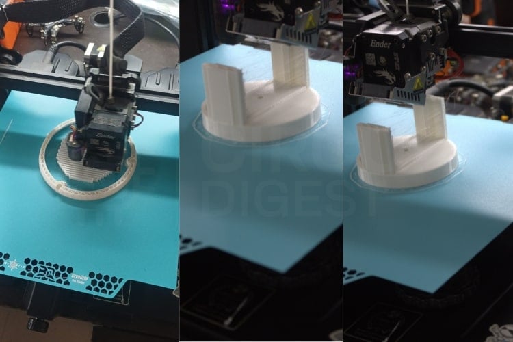
The 3D model was fabricated using a 3D printer for the Dual Axis Solar Tracker
![]()
This shows the 3D printed parts of the Dual Axis Solar Tracker
Arduino Code Explanation for Dual Axis Solar Tracking System
The program for this dual axis solar tracking system using Arduino is used to control two servo motors using feedback from four LDR sensors. It continuously compares light levels and rotates the servos to point the panel toward the brightest direction. When ambient light becomes too low, such as during nighttime, the system enters a standby mode to prevent unnecessary movement in this arduino dual axis solar tracker.
Servo Initialization
Two servo objects are defined to control horizontal and vertical movement in your arduino dual axis solar tracker. Their initial angles and movement limits are set to prevent over-rotation.
Servo horizontal;
Servo vertical;
LDR Sensors
Four LDR sensors are placed at the top-left, top-right, bottom-left, and bottom-right corners. They detect light intensity from each direction.
int ldrlt = A0;
int ldrrt = A3;
int ldrld = A1;
int ldrrd = A2;
Averaging Sensor Readings
This function reads each LDR multiple times and averages the result. It helps reduce noise and fluctuations in sensor readings.
int readAverage(int pin) {
 long total = 0;
 for (int i = 0; i < 10; i++) {
   total += analogRead(pin);
   delay(2);
 }
 return total / 10;
}
Light Difference Calculation
The code computes average light intensity on the top, bottom, left, and right sides to determine the direction of the brightest light source.
int avt = (lt + rt) / 2;
int avd = (ld + rd) / 2;
int avl = (lt + ld) / 2;
int avr = (rt + rd) / 2;
Servo Adjustment Logic
If the difference between top–bottom or left-right light levels exceeds a tolerance threshold, the servos move slightly to align the solar panel toward higher light intensity in the dual axis solar tracking system using arduino.
if (abs(dvert) > tol) { ... }
if (abs(dhoriz) > tol) { ... }
Night Mode
When ambient light is too low (e.g., at night), the system pauses tracking to save energy and prevent unnecessary movement.
if (avgLight < 200) {
 Serial.println("Low light detected — Tracker on standby...");
 return;}
Working Principle of Dual Axis Solar Tracker System
The dual axis solar tracking system working principle operates by constantly comparing light intensities from the four LDR sensors. When one side receives more sunlight than the other, the Arduino instructs the corresponding servo motor to rotate the panel toward that direction in this Arduino dual axis solar tracker. The horizontal servo controls east-west positioning, while the vertical servo adjusts north-south tilt.
This continuous adjustment allows the panel to maintain the most favourable position relative to the sun, significantly improving energy capture compared to fixed or single-axis systems. The process is automatic and adjusts throughout the day as sunlight shifts.
![]()
The full working setup of the Dual Axis Solar Tracker System Using the Arduino UNO
Tracking Algorithm Workflow for Dual Axis Solar Tracking System Using Arduino
∗ Light Sampling: All four LDR sensors take simultaneous light intensity readings.
∗ Data Processing: The Arduino averages the readings and computes horizontal and vertical differential light intensities.
∗ Decision Making: If the differential light intensities exceed tolerance, the system decides which direction it must move to optimise exposure.
∗ Servo Actuation: The horizontal servo determines east-west relative positioning of the panel, and the vertical servo changes the north-south tilt.
∗ Continuous Monitoring: This process is done every few seconds throughout the daylight hours to keep the solar panel always aligned optimally regardless of changing intensity.
Real-Time Tracking Demonstration
The animation below demonstrates the dual axis solar tracking system working in real-time. The figure below demonstrates Arduino dual axis solar tracker responds to changes in light direction.
![]()
The arduino dual axis solar tracker system actively responds to changes in light direction. When the light source is moved left, right, upward, or downward, the tracker responds instantly by rotating the panel in the corresponding direction, ensuring continuous alignment with the brightest point.
Comparison of Dual Axis Solar Tracker Over Fixed Systems
Compared to single-axis trackers, a dual axis solar tracker system offers significant performance improvements:
| Feature | Fixed Mount | Single-Axis Tracker | Dual-Axis Tracker |
| Energy Gain vs Fixed | 0% | 20-25% | 30-40% |
| Seasonal Adjustment | Manual | Manual | Automatic |
| Daily Sun Tracking | No | Yes (1 axis) | Yes (2 axes) |
| Morning/Evening Efficiency | Low | Medium | High |
| System Complexity | Low | Medium | Higher |
Conclusion of Dual Axis Solar Tracker
A clever and effective development in solar technology, the Dual Axis Solar Tracking System makes sure that solar panels are always facing the sun for optimal energy absorption. Compared to fixed and single-axis trackers, the system greatly increases power generation by intelligently adjusting in both horizontal and vertical directions using Arduino-controlled servos and LDR sensors. This tutorial teaches you how to build an arduino dual axis solar tracker that automatically follows the sun's position throughout the day. It is a useful and creative step toward a cleaner and more dependable energy future because of its adaptable design, which also increases efficiency and encourages sustainable energy use. The dual axis solar tracker Arduino project using ldr and servo motors demonstrates how affordable components and smart algorithms can dramatically improve solar panel efficiency. Finally, if you're curious about more solar projects, do check out our Simple Solar Powered Automatic Garden Light.
This tutorial was created by the CircuitDigest engineering team. Our experts focus on creating practical, hands-on tutorials to help makers and engineers learn Raspberry Pi projects, Arduino projects, IoT development projects and more.
I hope you liked this article and learned something new from building your Arduino dual axis solar tracker. If you have any doubts, you can ask in the comments below or use our CircuitDigest forum for a detailed discussion.
Frequently Asked Questions About the Arduino Dual Axis Solar Tracker System
⇥ 1. Why is a dual-axis solar tracker better than a fixed panel?
A dual-axis tracker can follow the sun both horizontally and vertically. This keeps the panel facing the sun throughout the day, which means it captures more sunlight and generates more energy compared to a fixed panel or even a single-axis tracker.
⇥ 2. Why are four LDR sensors used in this project?
Using four LDRs lets the system sense sunlight from all directions-left, right, top, and bottom. The Arduino then uses these readings to adjust the panel accurately along both axes in real time.
⇥ 3. Can the servo motors run directly from the Arduino?
No. Servo motors usually need more current than the Arduino can safely provide. Using a separate 5V power supply keeps the servos running smoothly and prevents damage to the board.
⇥ 4. What happens when the sunlight is weak or it’s nighttime?
If there isn’t enough light, the LDR readings drop below a certain level, and the tracker simply stops moving. This avoids unnecessary power usage and prevents wear on the servos.
⇥ 5. Do I need a 3D printer to build the frame?
Not at all. A 3D printer can make the frame look neat, but it’s not essential. You can use cardboard, PVC, or acrylic sheets-as long as the frame is sturdy and allows the servos to move freely.
⇥ 6. Is this dual-axis solar tracker functional under cloudy weather?
Yes, the dual-axis solar tracker can track diffuse sunlight through cloudy weather if adequate light differentials exist between the two sensor positions. However, if there is a dense, thick cloud, such as on a uniformly low-light day, the tracker may enter standby mode in response to extremely low lighting and/or minimal light differentials. Again, the averaging algorithm accounts for fluctuations that might result from clouding, and as such, it provides stable operational performance in tracking.
⇥ 7. What types of maintenance does a dual-axis solar tracker require?
The maintenance items to keep as a regular part of the dual axis solar tracker include: cleaning the light-dependent resistor (LDR) sensors and the solar panel surfaces, which could drift the accuracy of sensing light due to dust accumulating on the sensors and/or solar panel surface, checking deck-mounted connections to ensure there are no loose connections, observing the servicing of the servo motors, protecting electronic components from moisture by means of weather-resistant enclosures, and in some cases recalibrating the sensor thresholds when accuracy in tracking performance becomes degraded.
GitHub Repository
Visit the GitHub repository to download the source code, make modifications, and deploy the project effortlessly.


Learn faster by building real-world electronics projects for beginners designed and advanced makers.
More Solar-Based DIY Projects
Discover a range of practical solar-based DIY builds that demonstrate real-world applications of renewable energy and smart automation.

Solar Irradiance Measurement Meter
Here we will build a simple Arduino-based irradiance measurement device, test it using a live field and harvest the data and check how this reflects the result.
Sun Tracking Solar Panel using Arduino
In this article, we are going to make a Solar Panel Tracker using Arduino and two LDRs to sense the light and a servo motor to automatically rotate the solar panel in the direction of the sunlight

Multipurpose Solar Smart Plant Using ESP12E
Combatting air pollution in New Delhi with a Solar Smart Plant project. Learn how to build a DIY air quality monitoring system, detecting pollutants like carbon monoxide and nitrogen dioxide. Tackle environmental challenges and promote sustainability.
Complete Project Code
#include <Servo.h>
// ======== Servo Setup ========
Servo horizontal;  // Horizontal Servo Motor
Servo vertical;    // Vertical Servo Motor
int servohori = 180;  // Initial horizontal angle
int servovert = 45;   // Initial vertical angle
// Servo angle limits
int servohoriLimitHigh = 175;
int servohoriLimitLow  = 5;
int servovertLimitHigh = 100;
int servovertLimitLow  = 1;
// ======== LDR Pins ========
int ldrlt = A0; // Top Left LDR
int ldrrt = A3; // Top Right LDR
int ldrld = A1; // Bottom Left LDR
int ldrrd = A2; // Bottom Right LDR
// ======== Function: Read Average LDR Value ========
int readAverage(int pin) {
 long total = 0;
 for (int i = 0; i < 10; i++) {
   total += analogRead(pin);
   delay(2);  // small sampling delay for stable reading
 }
 return total / 10;
}
void setup() {
 Serial.begin(9600);
 Serial.println("=====================================");
 Serial.println("Dual Axis Solar Tracker System Started");
 Serial.println("=====================================");
 horizontal.attach(2);   // Horizontal servo pin
 vertical.attach(13);    // Vertical servo pin
 horizontal.write(servohori);
 vertical.write(servovert);
 delay(2000);
}
void loop() {
 // ======== Read and Filter LDR Values ========
 int lt = readAverage(ldrlt);  // Top Left
 int rt = readAverage(ldrrt);  // Top Right
 int ld = readAverage(ldrld);  // Bottom Left
 int rd = readAverage(ldrrd);  // Bottom Right
 // ======== Control Parameters ========
 int tol = 40;  // tolerance for movement (higher = less sensitive)
 int step = 2;   // servo movement step
 int avgLight = (lt + rt + ld + rd) / 4;
 // ======== Ignore at Low Light (Night Mode) ========
 if (avgLight < 200) {
   Serial.println("Low light detected — Tracker on standby...");
   delay(500);
   return;
 }
 // ======== Compute Averages ========
 int avt = (lt + rt) / 2;  // average of top sensors
 int avd = (ld + rd) / 2;  // average of bottom sensors
 int avl = (lt + ld) / 2;  // average of left sensors
 int avr = (rt + rd) / 2;  // average of right sensors
 // ======== Calculate Differences ========
 int dvert = avt - avd;   // vertical difference
 int dhoriz = avl - avr;  // horizontal difference
 // ======== Vertical Adjustment ========
 if (abs(dvert) > tol) {
   if (avt > avd) servovert += step;
   else servovert -= step;
   servovert = constrain(servovert, servovertLimitLow, servovertLimitHigh);
   vertical.write(servovert);
 }
 // ======== Horizontal Adjustment ========
 if (abs(dhoriz) > tol) {
   if (avl > avr) servohori -= step;
   else servohori += step;
   servohori = constrain(servohori, servohoriLimitLow, servohoriLimitHigh);
   horizontal.write(servohori);
 }
 // ======== Debug Output ========
 Serial.print("TL: "); Serial.print(lt);
 Serial.print("  TR: "); Serial.print(rt);
 Serial.print("  BL: "); Serial.print(ld);
 Serial.print("  BR: "); Serial.print(rd);
 Serial.print("  |  dV: "); Serial.print(dvert);
 Serial.print("  dH: "); Serial.print(dhoriz);
 Serial.print("  |  H: "); Serial.print(servohori);
 Serial.print("°  V: "); Serial.println(servovert);
 // ======== Small Delay for Stability ========
 delay(2);
}
Comments
I want to use 20 W solar panel for my project, suggest suitable servo to be used and any changes on code

Excellent and very practicle idea, have been working on this for few weeks on the similar idea for prototyping using audrino. Struck in making making the circuits work though, will try taking your learning.