

For those who have a keen interest in gardening, a garden light would provide an option to admire the beauty of their plants even during the night time. These lights will normally be placed inside the garden, far from electrical outlets because it is not a good idea to run wires through your garden soil which will be wet and toiled most of the time. This is where Solar-powered garden lights come into the picture. These lights will have a battery that will be charged through a solar panel in the day time and during the night time the energy from the battery will be used to power the lights and the cycle repeats. In some of our previous articles we have built few solar energy-related projects like solar-powered cell phone charger and solar inverter circuit.
In this project, we are going to build a simple and cheap DIY solar garden light. The solar panel will charge a lithium battery during day time and when it becomes night time, the battery will turn on the lights until its day time again. Unlike other circuits, we will not be using a microcontroller or sensor, because the idea of the project is to reduce the component count to reduce the price and complexity of the circuit. That being said let's start building our homemade solar light!!
Solar Garden Light Design
Before choosing the value of components and getting into the circuit diagram, it is essential to choose the load for our project. By load, we refer to the type of Garden Light that we will be using in our project. Because the voltage and current rating of the light decides how the circuit can be designed.
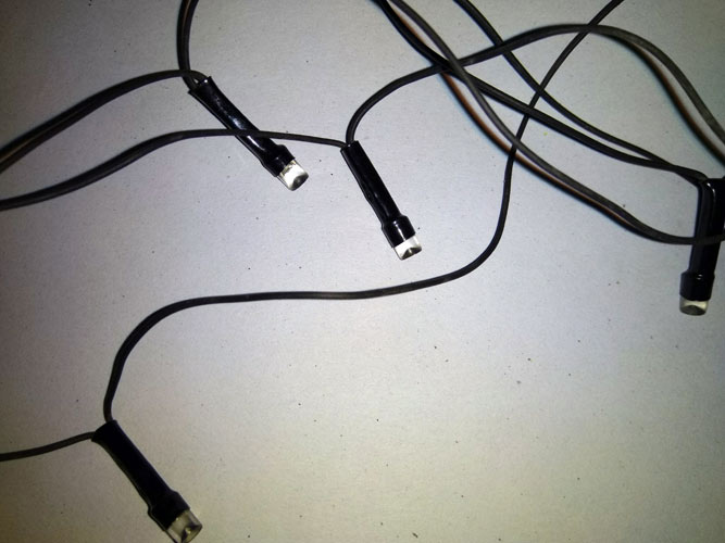
The LEDs we are using in this project are normal Chinese LEDs with an operating voltage of 3.2V with a maximum of 4.5V forward voltage. Therefore, if two LEDs are connected in series, the forward voltage will be 6.4V. The LEDs used in our project are shown below.
So a 7.4V lithium battery will be able to provide a minimum of 6.4V (fully discharged) to the maximum 8.4V (fully charged). Therefore, a 7.4V Lithium battery is used for a power source in this project, the same is shown below. If you are completely new to Lithium batteries, you can check out this Basics of Lithium-Ion Batteries article to understand better about batteries.
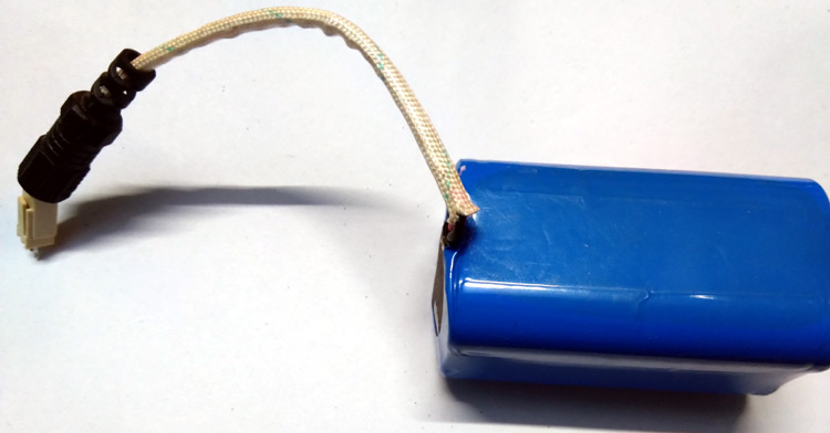
The battery which is selected for this application will have an inbuilt protection circuit that will protect the battery from overcharge, deep discharge, and short circuit related conditions. If your battery does not provide these features, make sure to use an external protection module, because lithium batteries can get highly unstable and might even explode if not handled properly.
Solar Garden Light Circuit Diagram
The solar garden light circuit will consist of two parts. One is charging and the other one is to control the LEDs. The complete circuit diagram is explained as two parts, the first part is given below

N-Channel MOSFET Q2, IRF540N is used for charge controlling operation. Potentiometer R1 is used to set the battery voltage level by controlling the gate voltage across the N Channel MOSFET Q2. The Schottky rectifier diode D1 is SR160, a 1A 60V Schottky diode that is used to protect the battery from reverse polarity as well as to block the reverse flow during discharging conditions. The output Schottky diode D2 is used to isolate the charger voltage with the battery voltage.
The other portion of the circuit is used to turn on the LED during dark conditions. This is done by the other P-Channel MOSFET Q1 which is IRF9540. The MOSFET gate is controlled by the solar voltage. Thus, whenever the solar cells produce voltage, the MOSFET remains turned off but in dark or at night, the cells do not produce voltage and the MOSFET gets turned ON. By using P Channel MOSFET, additional LDR and comparator circuit is completely eliminated.
Now, for the second part of the circuit, the LEDs are connected in a series-parallel condition. Two LED in series increases the forward voltage into double than a single LED, but the current flowing through LEDs gets divided. 4 parallel connections are made with two LEDs in series. More LEDs in parallel increase the current and affects the battery backup.
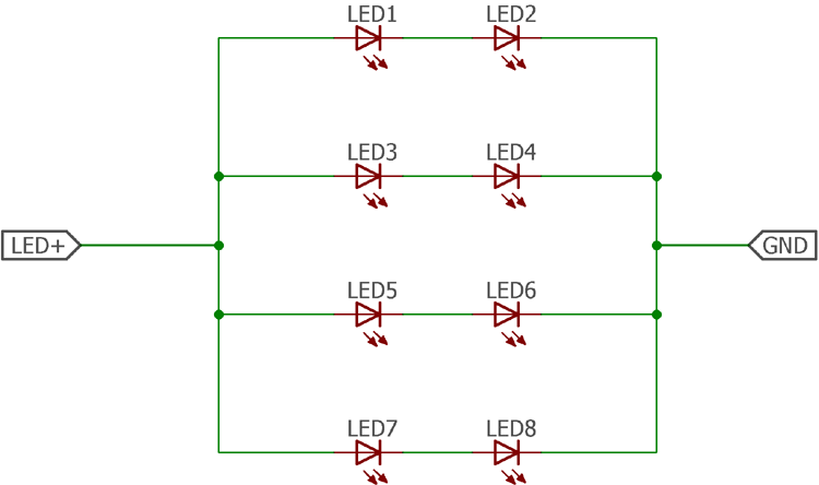
It is estimated that the current flow through each series is almost 40mA. Therefore, 4 parallel strings consume 160mA of current. The battery selected for this project will effectively light up the LEDs for almost 5-6 hours at a nominal charge condition. One can increase the LED strings as per needs.
Solar Garden Light Construction
To construct the circuit following components are required -
- Lithium battery 7.4V (mAH depends on the backup time) with an inbuilt protection circuit.
- LEDs with 3.5V forward voltage (Another voltage is also applicable but the LED strip construction will be different)
- IRF9540N – P channel Mosfet
- IRF540N – N Channel Mosfet
- SR160 Schottky diode 2 pcs
- 680R resistor
- 50k potentiometer
- 4.7k resistor
- Solar Panel 15 – 18V with more than 300mA current rating if a 3600mAH battery is selected.
- Wires for connecting solar panel and LEDs
- Hookup wires
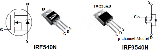
The below image shows the pinout of IRF540N N-channel and IRF9540 P-Channel Mosfet, that we will be using the project.
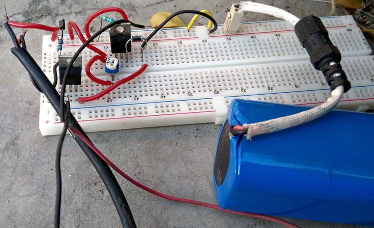
Once the Solar garden light circuit is constructed on a breadboard, my arrangement looks like this below
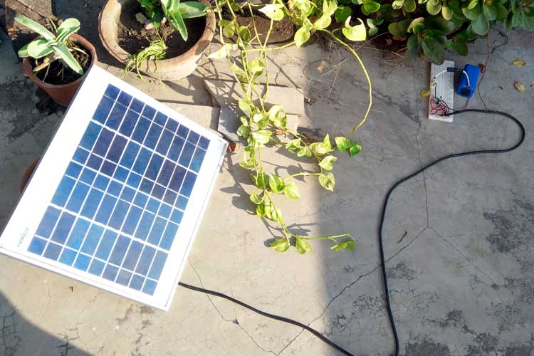
We have used the solar panel with the below specification.

It is a 10W solar panel with 18V output. The solar panel is placed in bright sunlight at peak solar conditions. The potentiometer is controlled to have 8.5V across the D2. This is due to the charging voltage as a lithium battery voltage will be 8.4V when it is fully charged. When the battery starts to charge an amp meter is connected in series with the battery to check the charge current. You can also improvise the project using a solar tracker to maximum battery charging, but that is something out of the scope of this project.
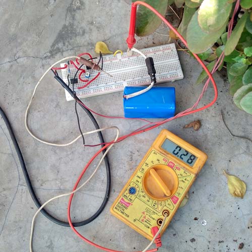
As you can check from the reading of the multimeter below, the charge current is almost 300mA. This change will be depending on the solar condition, it will increase on a sunny day and will go down on cloudy days.
During night time, when the solar panel receives no radiation, there will be no output current from the panel and hence the battery will stop charging and the LED lights will turn on. The complete working of the project can also be found in the video linked below, where we demonstrate of the light turns on automatically if the panel receives no radiation.
Further Improvements
The circuit is a basic lithium battery charger circuit for a simple garden light related project. Thus it does not employ any safety issues. For proper charging and employing proper solar charge method using MPPT (Maximum Power Point Tracker) dedicated driver ICs can be used.
As this is an outdoor operation project, proper PCB along with an enclosed box needs to be used. The Enclosure needs to be made in such a way that the circuit remains waterproof in rain. To modify this circuit or to discuss further aspects of this project, kindly use the active forum of the circuit digest.

Hello. I tried to use your solution with P-ch MOSFEt for a circuit with 3.7V Li-Ion battery and 4.5V solar panel, but it didn't work well. The dark detection is changing output LEDs light too slowly as light goes out and output is not max. Maybe the gate voltage that's driven from solar cell panel is too low?
Would you recommend some solution for this project?
(Actually I am trying to modify some Chinese Solar garden light with motion detector, to remove motion detection feature, but I couldn't get it to work because some control chip without marking is programmed to triger and keep output on just for 20 sec. Only connecting some repeating signal instead of PIR input would make it stay on constantly when dark.)