

There are lots of people working with renewable energy, especially Solar Power. However, the instruments required to properly predict the solar condition or how much power can be received from the sun in a given place is a crucial thing for successful Solar Operations. It is very useful to predict how much energy can be generated in a place and where to put the solar panel. The method used to predict this is Solar Irradiance measurement where estimation is required for how much power (in watt) is available in a square meter area. Now, this is generally done using the pyranometer which is a very costly instrument and makes no sense to use it for small MPPT or generic DIY Solar Panel projects where the cost of the project is not even 10% of the instrument.
Here, we will build a simple irradiance measurement device, test it using a live field and harvest the data and check how this is reflecting the result. This is a simple DIY solar irradiance meter project that will solve the purpose for non-commercial, DIY grade projects but it is good to explore the possibilities if this can be made using a simple light intensity sensor that provides luminance and then converting the same to an equivalent irradiance. Apart from this Irradiance Measurement Circuit, we have also built some other projects with Solar Panel like Solar Panel Power Monitoring, MPPT Solar Charge Controller, etc.
Components Required for Solar Irradiance Measurement Circuit
- Arduino Nano
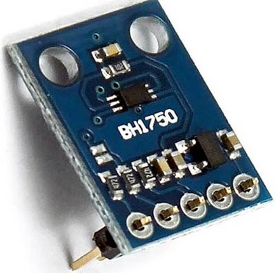
- BH1750 - Light Intensity Sensor Module
- Few strand wires or berg wires
- Arduino IDE and a PC
- Teraterm to log the Irradiance.
Selection of the Light Sensor
Well, the light sensor is very crucial for this project. There are multiple types of sensors available in the market that serve the purpose, even simple light-dependent resistors could measure flux but not accurately. There is also a requirement for a cost-effective, widely available solution to be fetched for this purpose. Thus, we have chosen the BH1750 as the light sensor. However, it is not used for direct sunlight measurement but it is useful for the Ambient light sensor where it supports a range of up to 65535 lx units. This is half of the luminance of a Brightest Sunlight.
Here is a closer value or maximum range of different conditions -
|
Case |
Illuminance |
|
Brightest Sunlight |
120000 Lux |
|
Bright Sunlight |
100000-110000 Lux |
|
Shaded Clear sky |
20000 Lux |
This sensor could provide a clear sky ambient light range and that could be converted to a typical irradiance that could be used for general purposes. So, it could provide a certain range of irradiance, technically. So, if a higher range of ambient light is used, then the full spectrum can be achieved. BH1750 is a Digital Ambient light sensor that uses I2C to communicate with the microcontrollers and works with 3.3V operation voltage.
Solar Irradiance Measurement Circuit
The complete schematic for building a Solar Irradiance circuit is given below:

The schematic is quite simple. The I2C is connected with the Arduino Nano. Fortunately, the BH1750 Board is having the pull-up resistor for the I2C thus no additional resistor is required. Powering the Arduino nano with 5V will provide 3.3V output on the 3.3V pin using the internal 3.3V regulator. The ADDR pin is set to ground making the default address of the BH1750 the I2C address of the sensor.
Programming Arduino Nano for Solar Irradiance Measurement
Here we have programmed Arduino nano to initialize the BH1750 object using the default high-resolution continuous mode and then make a light level reading every second. Complete code is given at the end of the document. Here we are explaining the complete code line by line.
So, as usual start the code by including all the required library files. Wire.h library is used to set up I2C communication between sensor and microcontroller while BH1750.h is used to read the BH1750 sensor data.
#include <Wire.h>
#include <BH1750.h>
Then inside the setup function, Initialize the I2C bus (BH1750 library doesn't do this automatically) and also initialize the serial monitor for debugging purposes.
void setup(){
  Serial.begin(9600);
  Wire.begin();
  lightMeter.begin();
  Serial.println(F("BH1750 Test begin"));
}
Here inside the void loop(), the Flux value that is received by the sensor is converted to the irradiance. There is no specific conversation for this, but an approximation can be made for the Sun wavelength. The flux can be converted to the approximate W/m2 using a multiplication of 0.079. A reference can be used from this thesis. Anybody who needs further explanation could refer to this for more information and it is a basic type of solar irradiance measurement.
After that, the received value from the sensor is printed on the UART port to store the data in an excel format for making a graph.
void loop() {
  float lux = lightMeter.readLightLevel();
  float irr = (lux*0.0079);
  Serial.print("irradiance: ");
  Serial.print(irr);
  Serial.println(" W/m2");
  delay(1000);
}
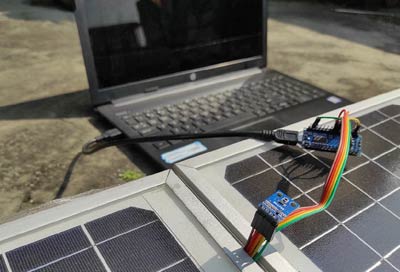
Testing the Solar Irradiance Measurement Circuit
Everything is connected in the place and it is tested in the reallocation. Fortunately, the day is well covered with sunny to shaded conditions all over the day. Thus, a clear result is reflected on the graph.
See the below image of how it is placed and the data is captured-
The data received from the light sensor is reflected on the below graph-
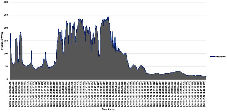
The above graph is showing a mixed cloudy days situation in West Bengal on the day of 27th October 2021 from the 12 PM to 2.45 PM data on a single graph.
Conclusion
Well, this is not exactly accurate but data can be recorded that is a very close approximation. If a proper sensor with full range is created. It is a basic project to reflect the solar irradiance for small and simple DIY projects that can be referenced. If you have any suggestions or have any question regarding this project you can post then in comment section or you can use our forum to start a discussion on it.
Complete Project Code
/*
  Example of BH1750 library usage.
  This example initialises the BH1750 object using the default high resolution
  continuous mode and then makes a light level reading every second.
  Connection:
    VCC -> 3V3 or 5V
    GND -> GND
    SCL -> SCL (A5 on Arduino Uno, Leonardo, etc or 21 on Mega and Due, on esp8266 free selectable)
    SDA -> SDA (A4 on Arduino Uno, Leonardo, etc or 20 on Mega and Due, on esp8266 free selectable)
    ADD -> (not connected) or GND
  ADD pin is used to set sensor I2C address. If it has voltage greater or equal to
  0.7VCC voltage (e.g. you've connected it to VCC) the sensor address will be
  0x5C. In other case (if ADD voltage less than 0.7 * VCC) the sensor address will
  be 0x23 (by default).
*/
#include <Wire.h>
#include <BH1750.h>
BH1750 lightMeter;
void setup(){
  Serial.begin(9600);
  // Initialize the I2C bus (BH1750 library doesn't do this automatically)
  Wire.begin();
  // On esp8266 you can select SCL and SDA pins using Wire.begin(D4, D3);
  // For Wemos / Lolin D1 Mini Pro and the Ambient Light shield use Wire.begin(D2, D1);
  lightMeter.begin();
  Serial.println(F("BH1750 Test begin"));
}
void loop() {
  float lux = lightMeter.readLightLevel();
  float irr = (lux*0.0079);
  Serial.print("irradiance: ");
  Serial.print(irr);
  Serial.println(" W/m2");
  delay(1000);
}

hello please I have a question base on this project solar irradiance. how are the pv cells connected to the light sensor or Arduino in other together the results because from the video. and the skeleton diagram I can't seem to see the use of the pv cells right next to the light sensors