
The biggest crisis we are heading into is climate change due to excessive use of fossil fuels, and to overcome these issues, we have only one solution, which is utilising Renewable Energy. Renewable energy is a type of energy that is harnessed from nature without causing ill effects to the environment. One of the most prominent kinds of renewable energy is solar energy. Solar radiation from the sun is collected by the solar panels and converted into electrical energy. The output electrical energy depends on the amount of sunlight falling on the solar panel.
If you have just started to work with Arduino, do check out our Arduino Projects and Tutorials. We have a collection of almost 500+ Arduino projects with Code, Circuit diagrams, and detailed explanations, completely free for everyone to build and learn on their own. This step-by-step tutorial illustrates how to build a sun tracking solar panel using Arduino that tracks the path of the sun automatically to achieve up to 35% more energy harvesting than fixed panels. Our solar panel monitoring system using Arduino project, employs basic components and tried-and-tested code to design an efficient, low-cost solution for increased solar power generation.
Traditionally, solar panels are fixed, and the movement of the sun over the horizon means that the solar panel does not harness maximum energy most of the time. In order to maximise the power from the solar panel, the panel should face the sun at all times. In this project, we will make a sun tracking system using Arduino, which will help the solar panels generate maximum power. In some of our previous articles, we have built a simple system to track power generated from solar panels and other solar energy-related projects. You can check those out if you are looking for more projects on solar power.
Table of Contents
How Does an Arduino-Based Solar Tracking System Work?
You must be wondering how it works. As discussed earlier, the solar panel should face the sun to harness maximum power. So, our system has two steps, first is to detect the position of the sun, and second is to move along with it.
Sun Position Detection Methodology
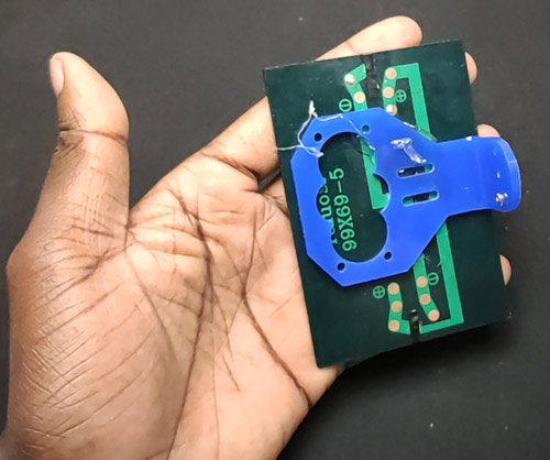
We measure the intensity of light with LDRs using Arduino and compare the intensity of light falling on both LDRs. The LDRs are placed on the edges of the solar panel as shown in the figure below.
Based on the intensity of light on the LDR, we give the signal to the servo motor to cause the movement. When the intensity of the light falling on the right LDR is higher, the panel turns towards the right, and if the intensity is higher on the left, then the panel slowly turns towards the left side.
![]()
Consider a scenario of a beautiful winter morning, the sun rises from the east side and therefore it has more light intensity than the west side, so the panel moves towards to east side. Throughout the day, it will track the sun and by the evening, the sun has moved towards the west, hence it will have more intensity than the east direction, so the panel will face the west direction.
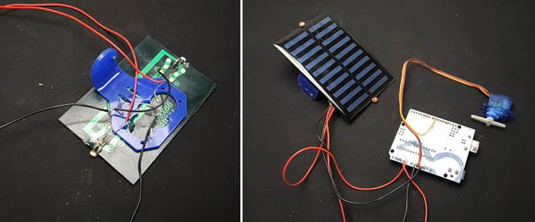
Essential Components for Arduino Solar Tracker
![]()
- 1 x Arduino Uno
- 1 x Servo motor
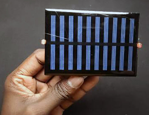
- 1 x Solar panel
- 2 x LDR
- 2 x 10k Resistor
- Jumper wires
- 1 x MDF board
Servo Motor:
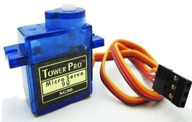
A servo motor is used to rotate the solar panel. We are using a servo motor because we can control the position of our solar panels precisely, and it can cover the whole path of the sun. We are using a servo motor that can be operated with 5 volts.
Servo Motor Technical Specifications
Parameter | Specification | Application Benefit |
|---|---|---|
Operating Voltage | 4.8V - 6V | Direct Arduino power compatibility |
Rotation Range | 0° - 180° | Complete sun path coverage |
Torque | 2.5 kg⋅cm | Sufficient for small solar panels |
Speed | 0.1s/60° | Smooth tracking movement |
Light Dependent Resistor (LDR):
A light-dependent resistor is made from a semiconductor material having light-sensitive properties and is hence very sensitive to light. The resistance of LDR changes according to the light that falls on it, and it is inversely proportional to the intensity of light. That is resistance of the LDR will increase at high-intensity light and vice versa.
Circuit Diagram of Solar Tracking System Using Arduino
The Circuit diagram of solar tracking system using Arduino shows a simple connection setup with very few components external to Arduino. This design is as simple as possible but retains a core to deliver an efficient performance as a solar tracker. The connection of the circuit is very straightforward. Here, I used an Arduino Uno as a controller and connected the 2 LDRs to analogue pins A0 and A1, respectively. Pin 9 of Arduino is connected to the servo motor. Since we have used a 5V servomotor, we don’t require any external power supply because all the components can easily be powered by the Arduino itself. All the connections are shown in the figure below.
![]()
Solar Panel Monitoring System Using Arduino - Benefits
The schematic diagram of a Solar Panel Monitoring System Using Arduino shows that it's an open circuit, clean layout with an efficient design that minimises components while providing maximum value. This not only reduces unnecessary failure points, but it also makes troubleshooting easier.
» One embedded power source: everything runs from the Arduino 5V source.
» Very few external components: only resistors and connecting wires.
» Good, reliable connections: taking advantage of digital and analog pins.
The sun tracking solar panel using Arduino block diagram shows how we measure light intensity using strategically positioned LDRs on opposite edges of the solar panel.
Solar Tracking System Arduino - Assembling
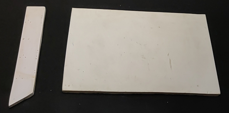
Constructing a stable base guarantees the consistent functioning of your sun tracking solar panel using Arduino project. Adhere to these elaborate assembly steps for peak mechanical performance. The first step before assembling our solar tracker is to construct the base. For building the base, I am going to use an MDF board. First step is to cut and make rectangular pieces of 12*8cm and 12*2cm from the MDF board as shown in the figure.
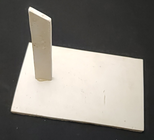
Then stick 12*2cm piece vertically to the 12*8cm piece as shown in the image.
The next step is to attach the solar panel to the servo motor; for that, we require the L-shaped contraption. For this, I am using a plastic piece. You can also make this by bending a plastic sheet or an aluminium sheet, and finally glue the solar panel to your contraption.
Note: If you are going to make a tracker for a large solar panel, then you should use different materials for bases, such as aluminium or wood.
Now, we need to affix the LDRs on opposite sides of the solar panel and to do that, I glued the LDRs to the panel. Then, I connected the 10k resistors to one of the leads of both LDRs, and the other side of the resistor should be connected to the ground. These are acting as pull-down resistors. The second terminal of the LDRs is directly connected to the 5V output. The output of each LDR, I connected it to the A1 and A2 pins of the Arduino.
Next step is to connect the servo motor, a servo motor has three wires, i.e. ground, V_in and a signal wire. I connected the V_in pin to the 5V of Arduino, ground to the common ground and the signal wire to pin 9 of Arduino. That's all about the circuit.
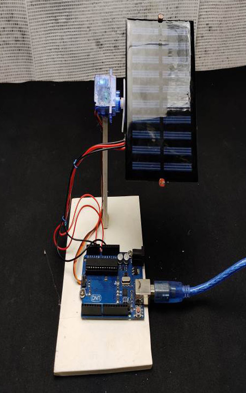
Now, all we have to do is assemble everything. First, I glued the Arduino on the base sheet. Then I attached the servo motor to the vertical section using a glue gun. Finally, I fixed the solar panel with the servo motor’s hand and secured it with a screw.
![]()
Solar Tracker Arduino Code: Complete Programming Guide
The solar tracker Arduino code we optimised features error detection, calibration, and controlled servos for performance robustness. The programming logic governs sun tracking while protecting the servo motor from excessive stress.
Code features and functionality
- Automatic calibration for multiple LDR sensitivities
- Error thresholds to eliminate pointless errors
- Night mode with automatic reset in the morning
- Servo position limits to protect mechanical components
The complete code for this project can be found at the bottom of this page. The first step before writing the code is to download the Servo Library. We need a servo library to control the motion of the servo. The step-by-step explanation of the program is given below.
#include <Servo.h>
Servo servo ;
First, I included the servo library and created a servo object and named it ‘servo’.
int eastLDR = 0;
int westLDR = 1;
int east = 0;
int west = 0;
int error = 0;
Code Calibration and Fine-Tuning
Position setup: Place your light source directly overhead of your solar panel.
Read values: Examine the Serial output for both LDR reading values.
Calculate the difference: Observe any variation between the east and west sensors.
Use calibration: Change the data variable for calibration to allow both readings to be equal.
Test operation: Confirm that both directions track smoothly.
Here, I have assigned the analogue pins A0 and A1 for LDR and declared the variables for sensor values.
int calibration = 0;This variable is for calibrating the system. If you are using the same LDRs on both sides, then you can leave it as zero. But if you are using different LDRs, then you should use this to calibrate. To calibrate, follow the instructions in the next paragraph.
Serially print the sensor values and check the reading of each sensor at noon, or place a light source just above the solar panel. If the reading shows the same values, then you can leave this as it is, and if it shows any difference, then you have to copy those values here.
int servoposition = 90;This variable is to store the servo position.
void setup()
{
  servo.attach(9);
 }
In this section, I have defined the servo pin as pin 9
east = calibration + analogRead(eastLDR);
west = analogRead(westLDR);
In the loop section, the first step is to read the LDR values using the analogue read function of Arduino and store it in east and west variables.
if(east<350 && west<350)
  {
 while(servoposition<=150)
  {
servoposition++;
servo.write(servoposition);
delay(100);
    }
This if condition is for turning the solar panel back to the east side, i.e. if both the LDRs read a low value, then the panel moves towards the east side.
error = east - west;Here, we calculate the difference between east and west readings. If the error value is positive, that means east has more intensity, and if the error is negative, then west has higher intensity of light. So, according to this error value, we can rotate the servo to the low-intensity side.
if(error>30)
  {
 if(servoposition<=150)
{
servoposition++;
 servo.write(servoposition);
}
  }
If the error is positive and greater than 30, it means that the east side has more intensity. So, initially, the system will check the starting position of the servo, and if it is less than 150 degrees, then it rotates to the east direction. You can adjust these angles according to your system.
 else if(error<-30)
  {
 if(servoposition>20)
{
 servoposition--;
 servo.write(servoposition);
  }
If the error is negative and less than -30, that means the west side is more intense, hence the servo rotates to the west side.
So, that's all about coding. Now you can open this code on your Arduino IDE and upload the sketch to your Arduino.
![]()
Troubleshooting Common Issues
Issue | Possible Cause | Solution |
|---|---|---|
| No servo movement | Power supply insufficient | Check Arduino USB connection and servo wiring |
| Erratic tracking | LDR sensitivity mismatch | Adjust the calibration value in the code |
| Servo jitter | Noise in analog readings | Add a capacitor across the LDR connections |
| Limited rotation range | Mechanical obstruction | Check the servo mounting and cable routing |
Technical Summary and GitHub Repository
Here you can find the technical breakdown of the project, from circuit design to code structure. It's meant to help you understand how everything works together, whether you're replicating or modifying it. Full project resources and code are hosted in our GitHub repository.


Frequently Asked Questions on Solar Tracking System Arduino
⇥ How much more power can I expect a solar tracker to produce compared to a fixed panel array?
Arduino-based solar trackers typically generate 25-35% more energy than fixed panel solar systems. If you need a cost-effective solution, single-axis tracking delivers the most value. Dual-axis trackers can produce nearly a 40% improvement in output, but at the cost of added complexity.
⇥ Can an Arduino solar tracker work in cloudy weather?
Yes, Arduino solar trackers will still function well when cloudy, as they can determine where the brightest part of the sky is located. LDR sensors are still sensitive enough to track the diffused sunlight. The system has built-in low-light thresholds to prevent oscillating during overcast conditions.
⇥ How powerful a solar panel can an Arduino tracker handle?
Standard SG90 servo motors can handle solar panels up to 1-2 watts (about 300mA at ~6V). Mini high-torque servo motors are utilised for larger panels. Mechanical Actuators are used for larger solar panels. If the solar panels are more than 5 watts, refer to professional installation and employ a separate power supply with relay control.
⇥ How do I calibrate LDR sensors for effective tracking?
Calibration is simply placing the same light source above both LDRs and checking the serial output readings. Take the difference between the 2 sensors and adjust the calibration variable in the Arduino code so they read equal. Use this calibration constant to correct any variation in the difference of the LDR's measurement.
⇥ Am I able to use an Arduino solar tracker outdoors?
Basic Arduino solar trackers require weatherproofing to sustain outdoor conditions. Put the Arduino in a waterproof enclosure, use marine-grade wiring, coat the MDF with varnish, and use components rated for the temperatures listed if these are very extreme. Any professional installations should use aluminium frames.
I hope that you enjoyed this project. It has a lot of applications in real life, and it is implemented in a lot of solar farms and individual solar harnessing setups. You can enhance the scope of this project by replacing the 5V servo motor with a high-torque servo motor and connecting it using a relay and powering the servo from an external source. As mentioned above, if you are having bigger solar panels, then you will have to use stronger material, such as aluminium, for the base.
Related Projects: Solar Power Innovations
Enhance your understanding of solar energy solutions with these diverse and innovative projects. From tracking solar panel efficiency to real-time monitoring of battery systems and solar power performance, these projects combine cutting-edge technology and sustainability for a smarter future in renewable energy.

IoT based Lithium Battery Monitoring System using ESP8266
The aim of this project is to monitor a Lithium Battery Bank remotely in a solar installation. It traces current individually for each Battery Pack. It also communicates with solar charger and calculates live values of power going to home and battery bank.

IoT-based Solar Power Monitoring System using ESP32 and ThingSpeak
In this project, we will be making an IoT-based Solar Power Monitoring System by incorporating the MPPT (Maximum Power Point Tracker)-based battery charging technique, which will help to reduce charging time and improve efficiency.

Solar Irradiance Measurement Meter
Here we will build a simple Arduino based irradiance measurement device, test it using a live field and harvest the data and check how this is reflecting the result.
Complete Project Code
#include <Servo.h>
Servo servo ;
int eastLDR = 0;
int westLDR = 1;
int east = 0;
int west = 0;
int error = 0;
int calibration = 600;
int servoposition = 90;
void setup()
{
  servo.attach(9);
}
void loop()
{
  east = calibration + analogRead(eastLDR);
  west = analogRead(westLDR);
  if (east < 350 && west < 350)
  {
    while (servoposition <= 150)
    {
      servoposition++;
      servo.write(servoposition);
      delay(100);
    }
  }
  error = east - west;
  if (error > 15)
  {
    if (servoposition <= 150)
    {
      servoposition++;
      servo.write(servoposition);
    }
  }
  else if (error < -15)
  {
    if (servoposition > 20)
    {
      servoposition--;
      servo.write(servoposition);
    }
  }
  delay(100);
}

Hi, nice project! I am having issues with the servo not tracking. It only rotates to one side and stays there. Can you point me towards the right direction for troubleshooting it? Thanks!