
Pulse Width Modulation (PWM) is a powerful technique where width of the pulse is changed by keeping the frequency constant. The technique is used in many control systems today. The application of PWM is not limited and it is used in wide range of applications such as motor speed control, measurement, power control and communication etc. In PWM technique, one can easily generate analog output signal using digital signals. This tutorial will help you in understanding PWM, its terminologies and how we can implement it using a microcontroller. In this tutorial we will be demonstrating PWM with AVR Atmega16 Microcontroller by varying the intensity of an LED.
To understand the basics of PWM in detail, please go to our previous tutorials on PWM with various microcontrollers:
- ARM7-LPC2148 PWM Tutorial: Controlling Brightness of LED
- Pulse width Modulation (PWM) using MSP430G2: Controlling Brightness of LED
- Generating PWM using PIC Microcontroller with MPLAB and XC8
- Pulse width Modulation (PWM) in STM32F103C8: Controlling Speed of DC Fan
- Generating PWM signals on GPIO pins of PIC Microcontroller
- Raspberry Pi PWM Tutorial
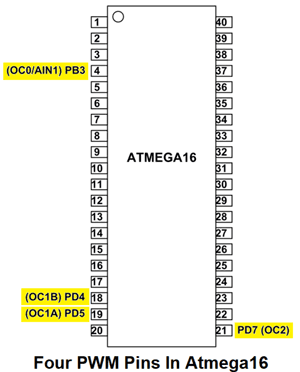
PWM Pins in AVR Microcontroller Atmega16
Atmega16 has four dedicated PWM pins. These pins are PB3(OC0), PD4(OC1B), PD5(OC1A), PD7(OC2).
Also Atmega16 has two 8-bit timers and one 16 bit timer. Timer0 and Timer2 are 8-bit timers whereas Timer1 is 16-bit timer. To generate PWM we must have an overview of timers as timers are used to generate PWM. As we know that the frequency is number of cycles per second that the timer runs at. So the higher frequency will give us a faster timer. In generating PWM, a faster PWM frequency will give finer control over the output because it can respond faster to new PWM duty cycles.
In this Atmega16 PWM tutorial we will use Timer2. You can choose any duty cycle. If you don’t know what is duty cycle in PWM then let’s discuss in brief.
What is a PWM Signal?
Pulse Width Modulation (PWM) is a digital signal which is most commonly used in control circuitry. The time during which the signal stays high is called the “on time” and the time during which the signal stays low is called the “off time”. There are two important parameters for a PWM as discussed below:
Duty cycle of the PWM
The percentage of time in which the PWM signal remains HIGH (on time) is called as duty cycle.
Like in 100ms pulse signal, if the signal is HIGH for 50ms and LOW for 50ms, it means the pulse was half time HIGH and half time LOW. So we can say that the duty cycle is 50%. Similarly if the pulse is in 25ms HIGH state and 75ms in LOW state out of 100ms, then the duty cycle would be 25%. Notice that we only calculate the duration of HIGH state. You can take reference of below picture for visual understanding. The formula for duty cycle is then,
Duty Cycle (%) = On Time/(On Time + Off Time)
So, by changing the duty cycle we can change the width of PWM thus resulting in change of LED brightness. We will have demo of using different duty cycle in controlling brightness of LED. Check the demo Video at the end of this tutorial.
After selecting the duty cycle, next step would be selecting the PWM mode. The PWM Mode specifies that how do you want PWM to work. There are mainly 3 types of PWM modes. These are as follows:
- Fast PWM
- Phase Correct PWM
- Phase and Frequency Correct PWM
Fast PWM is used where the phase change does not matter. By using Fast PWM, we can output the PWM values rapidly. Fast PWM can’t be used where phase change effects the operation such as motor control, so in such application other Modes of PWM are used. Since we will be controlling Brightness of LED where phase change won’t affect much, so we will use Fast PWM mode.
Now to generate PWM we will control the internal timer to count up and then set back to zero at a particular count, so timer will count up and then set back to zero over and over again. This sets the period. We now have the option of controlling a pulse, turning a pulse ON at a specific count in the timer while it goes up. When the counter goes back to 0, then turn off the pulse. There is lot of flexibility with this because you can always access the count of the timer and provide different pulses with a single timer. This is great when you want to control multiple LED’s at once. Now let’s start interfacing one LED with Atmega16 for PWM.
Check all the PWM related projects here.
Components Required
- Atmega16 AVR Microcontroller IC
- 16Mhz Crystal Oscillator
- Two 100nF Capacitors
- Two 22pF Capacitors
- Push Button
- Jumper Wires
- Breadboard
- USBASP v2.0
- 2 Led(Any Color)
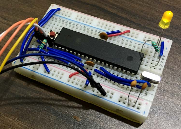
Circuit Diagram

We are using OC2 for PWM i.e Pin21 (PD7). So connect one LED at PD7 pin of Atmega16.
Programming Atmega16 for PWM
Complete program is given below. Burn the program in Atmega16 using JTAG and Atmel studio and see the PWM effect on LED. Its brightness will increase and decrease slowly because of varying duty cycle of PWM. Check the Video given at the end.
Start programming Atmega16 with setting up Timer2 Register. The Timer2 register bits are as follows and we can set or reset bits accordingly.

Now we will discuss about all the bits of Timer2 so we can get desired PWM using written program.
There are mainly four parts in Timer2 register:
FOC2 (Force Output Compare for Timer2): The FOC2 bit is set when the WGM bits specify a non-PWM Mode.
WGM2(Wave Generation Mode for Timer2): These bits control the counting sequence of the counter, the source for the maximum (TOP) counter value, and what type of waveform generation to be used.
COM2 (Compare Output Mode for Timer2): These bits controls the output behaviour. The complete bit description is explained below.
TCCR2 |= (1<<WGM20)|(1<<WGM21);
Set WGM20 and WGM21 bits as HIGH to activate PWM Fast Mode. The WGM Stands for Waveform Generation Mode. The selection bits are as below.
WGM00 | WGM01 | Timer2 Mode Operation |
0 | 0 | Normal Mode |
0 | 1 | CTC(Clear Timer On Compare Match) |
1 | 0 | PWM, Phase Correct |
1 | 1 | Fast PWM Mode |
For more details on Waveform Generation Mode, you can refer official datasheet of Atmega16.
TCCR2 |=(1<<COM21)|(1<<CS20)|(0<<CS21)|(0<<CS22);
Also we haven’t used any pre-scaling so we have set Clock source register as ‘001’.
The Clock selection bits are as follows:
CS22 | CS21 | CS20 | Description |
0 | 0 | 0 | No clock source(Timer/Counter stopped) |
0 | 0 | 1 | clkT2S/(No Prescaling) |
0 | 1 | 0 | ClkT2S/8(From Prescaler) |
0 | 1 | 1 | ClkT2S/32(From Prescaler) |
1 | 0 | 0 | ClkT2S/64(From Prescaler) |
1 | 0 | 1 | ClkT2S/128(From Prescaler) |
1 | 1 | 0 | ClkT2S/256(From Prescaler) |
1 | 1 | 1 | ClkT2S/1024(From Prescaler) |
Also OC2 is cleared on compare match by setting COM21 bit as ‘1’ and COM20 as ‘0’.
The Compare Output Mode (COM) selection options for Fast PWM Mode is given below:
COM21 | COM21 | Description |
0 | 0 | Normal port operation, OC2 disconnected. |
0 | 1 | Reserved |
1 | 0 | Clear OC2 on Compare match, Set OC2 at TOP |
1 | 1 | Set OC2 on compare match, clear OC2 at TOP |
Increase the duty cycle from 0% to 100% so the brightness will increase over the time. Take value from 0-255 and send it to OCR2 pin.
for(duty=0; duty<255; duty++)   // 0 to max duty cycle
{
 OCR2=duty;     //slowly increase the LED brightness
 _delay_ms(10);
       }
Similarly decrease the duty cycle from 100% to 0% to gradually decrease the brightness of LED.
for(duty=0; duty>255; duty--)   // max to 0 duty cycle
 {
 OCR2=duty;     //slowly decrease the LED brightness
 _delay_ms(10);
  }
This finishes our Tutorial on Using PWM in Atmega16/32.
Complete Project Code
/*
 * LED brightness control using Atmega16
 */
#define F_CPU 16000000UL             //define CPU frequency
#include "avr/io.h"
#include <util/delay.h>

void PWM_set(){                                 // PWM setup function

 DDRD |= (1<<PD7);                              //set PD7 as PWM output
 TCCR2 |= (1<<WGM20)|(1<<WGM21);                //select Fast PWM mode by setting bits
 TCCR2 |=(1<<COM21)|(1<<CS20)|(0<<CS21)|(0<<CS22);   //clear OC2 on compare match
    }

int main ()
{
 unsigned char duty;
 PWM_set();         //call PWM setup function
       while (1)
       {
for(duty=0; duty<255; duty++)   // 0 to max duty cycle
{
 OCR2=duty;     //slowly increase the LED brightness
 _delay_ms(10);
       }
for(duty=0; duty>255; duty--)   // max to 0 duty cycle
 {
 OCR2=duty;     //slowly decrease the LED brightness
 _delay_ms(10);
  }
 }
}

Hi, good work here.
I recently worked on a project similar to this one on Arduino, using the special registers of the AtMega328.
I found a solution that might make the program work better. In your code you update the OCR2 every 10 milliseconds in order to see the fading of the LED.
I suggest to update OCR2 in respect to a set of values calculated in setup() in a Interrupt Service Routine triggered by the overflow of the timer, when the counter reaches TOP.
I know that for this particular application my idea doesn't fit well, but it will be useful when having to generate a PWM for general purpose, for example waveform generation.
Cheers