
Thermostat is formed by summing two Greek terms thermo and statos, thermos means heat and statos means stationary, standing, or fixed. Thermostat is used to control the devices or home appliances according to the temperature, like turn on/off air conditioner, room heaters etc. Common applications of thermostat are to maintain room temperature in centralized heating systems or cooling system, regulating refrigerator temperature, cooling system, electric iron, ovens, hair dryers and many more. Programmable and smart thermostats are also available in the market today.
Types of Thermostat:
To sense the temperature, different Thermostats use different sensor or devices, and according to that they can be mainly classified into two types
- Mechanical Thermostat
- Electrical/Electronic Thermostat
Mechanical Thermostat -
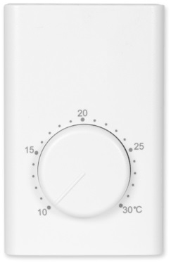
Bimetal Thermostat falls under mechanical thermostat. Generally they have a casing and a knob like shown in below picture. It has one fixed contact and one movable liver which is composed of two different metals having different coefficients of linear expansion. The end of the movable lever get connected with fixed contact when temperature decrease, and get disconnected when room temperature is high. That is how it can turn on and off the devices according to the temperature.
Some examples where bimetal thermostats are used - iron, refrigerator, air conditioner.
Electrical Thermostat -
The most common electronic temperature sensors are thermocouples and thermistors used in thermostat. Both thermistor and thermocouple electrical properties experience change when exposed to temperature variation.
Thermocouple is a device which uses at least two different metal strips that are joined at one end to form two junctions; hot junction and cold junction. Hot junction is a measuring junction; object whose temperature is to be measured is placed at Hot junction, whereas Cold junction (whose temperature is known) is the reference junction. Due to this temperature difference a voltage difference is generated known as thermoelectric voltage which is used to measure the temperature. Thermocouple are used in boilers, ovens etc.
The other type of electrical sensor used in thermostat is thermistor which we are going to study further in detail with example.
What is a Thermistor?
As the name suggests a thermistor is a combination of two words, Thermal and Resistor. It’s a resistive component whose resistance varies with change in temperature.
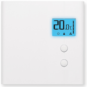
Thermistors are highly reliable and have a wide range of scale to detect minor temperature variation preciously. They are cheap and useful as temperature sensor. Thermistor is used in digital thermostat.
Types of Thermistor
Depending on its resistance variation with respect to the surrounding temperature, there are two types of thermistors. They are explained in detail below:-
1. PTC – Positive Temperature Coefficient.
Its resistance is directly proportional to the temperature i.e., its resistance decreases with decrease in temperature and vice-versa.
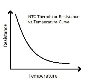
2. NTC - Negative Temperature Coefficient.
Its resistance is indirectly proportional to the temperature i.e., its resistance decreases with increase in temperature and vice-versa.
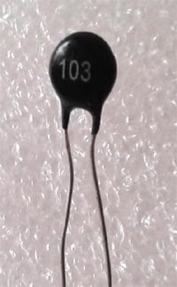
We are using NTC thermistor in our application. 103 is indicating the resistance of thermistor at normal temperature means 10k Ohm.
Application of NTC thermistor:
To be able to control any device based on the temperature variation is a very convenient and interesting idea. One such popular application is Fire alarm, where thermistor senses the heat and trigger the alarm.
NTC thermistors are most widely used in various applications but where there is requirement of low resistance at starting point, PTC thermistor are used.
The resistance of thermistor at room temperature is specified by the manufacturer in the datasheet along with the different set of values of resistances at different temperature, thereby one can choose the right thermistor for appropriate application.
Here are some circuits built by using Thermistor:
- Fire Alarm using Thermistor
- Temperature Controlled DC Fan using Thermistor
- Interfacing Thermistor with Arduino to Measure and Display Temperature on LCD
- Temperature Controlled AC Home Appliances
Component required:
- NTC 103 thermistor (10k Ω).
- BJT BC 547.
- 5k Ω Potentiometer (POT).
- 1kΩ Resistor.
- LED.
- Power Supply – 6V DC.
- Breadboard and connecting wires.
Circuit Diagram of Thermistor Circuit:

Working of Thermostat Circuit:
The circuit compromises of a voltage divider circuit and output “ON and OFF” switching circuit. Voltage divider circuit is formed by the thermistor and a variable resistor.
Voltage divider circuit output is connected to the base of NPN transistor through a 1k resistor. Voltage divider circuit makes it possible to sense the variation in voltage caused by variation in resistance of Thermistor. By using a POT in the voltage divider, we can adjust the sensitivity of thermistor. You can also use a fixed resistor in place of Variable resistor for a fix triggering point, means the LED will be switched On, only if temperature crosses a particular value and you can’t be able to adjust the triggering point temperature. So better use a POT and vary the sensitivity by just rotating the knob.
One can select the set of resistors by the formula below-
Vo = [R2 / (R1 + R2)] × VIN
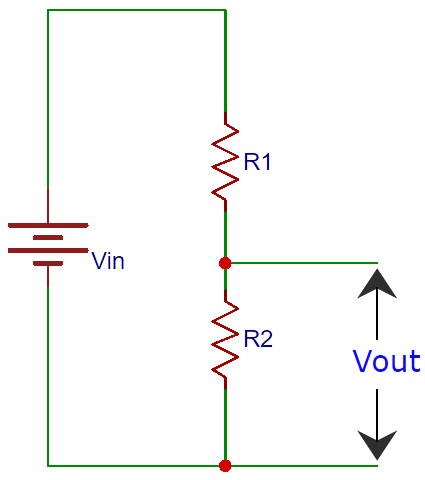
In our circuit, we have replaced R2 with POT and R1 with LDR, so the output voltage changes with the Thermistor resistance. And thermistor resistance changes with outside temperature, so the output voltage will change as we change the temperature around thermistor. The transistor will turn on at 0.7 V or above which is the VBE voltage.
A simpler way, to select and know appropriate R2 for 10k NTC thermistor, is to simulate the circuit in Proteus and get a close value of R2. Also by replacing thermistor with a variable resistor we can study its equivalent effect in the circuit as per the below circuit diagrams:
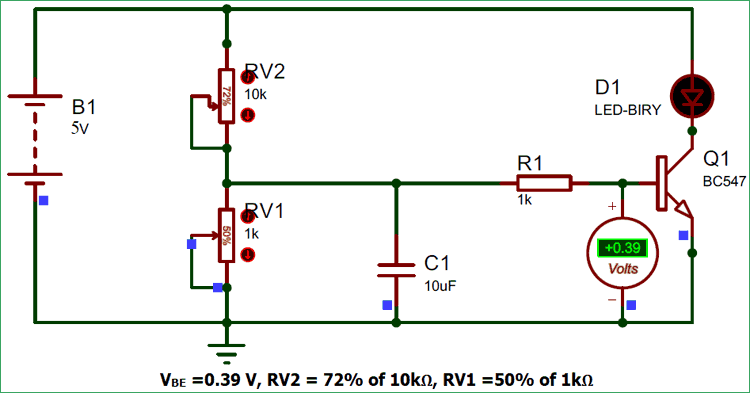
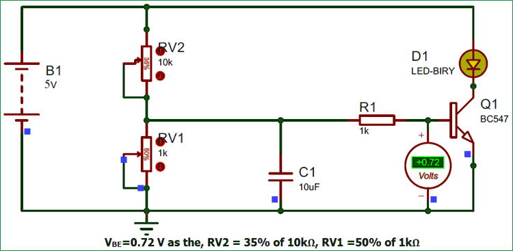
The second part of the circuit is transistor section where transistor acts as a switch for LED D1. Since a transistor is a current controlled device, a resistor R1 is connected to its input terminal to limit the current surge.

Referring to the above simulation circuit, as soon as the temperature rises near the thermistor its electrical resistance decreases, resulting voltage increase across RV1. So the voltage at base of transistor (VBE) also increase, and as soon as the VBE ≥0.7 V the transistor starts conducting and LED will be turned On.
Please note we can replace this LED with a buzzer or bulb etc. in the above circuit with minimal addition of few more components. Also check the Demo Video below.
