

“Automation is good, so long as you know exactly where to put the machine’’, In this tutorial we are making a Temperature controlled DC fan using Thermistor, as it starts above the preset level of temperature and stops when the temperature return to normal condition. This whole process is done automatically. We have previously made the Temperature controlled Fan using Arduino, where the speed of the fan is also controlled automatically.
Required Components
Below components are required for this Automatic Fan Controller using Thermistor:
- Op amp IC LM741
- NPN Transistor MJE3055
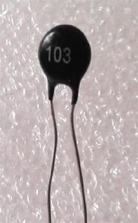
- NTC Thermistor - 10k
- Potentiometer – 10k
- Resistors - 47 Ohm, 4.7k
- DC Fan (Motor)
- Power supply-5v
- Breadboard and connecting wires
Circuit Diagram
Below is the circuit diagram for Temperature Controlled Fan using Thermistor as Temperature Sensor:

Thermistor
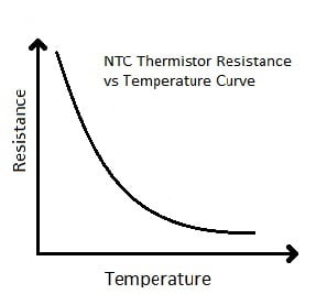
The key component of this temperature controlled fan circuit is Thermistor, which has been used to detect the rise in temperature. Thermistor is temperature sensitive resistor, whose resistance changes according to the temperature. There are two types of thermistor NTC (Negative Temperature Co-efficient) and PTC (Positive Temperature Co-efficient), we are using a NTC type thermistor. NTC thermistor is a resistor whose resistance decreases as rise in temperature while in PTC it will increase the resistance as rise in temperature. We also used Thermistor in many interesting applications like Fire alarm circuit using Thermistor, Temperature Controlled AC, Thermistor Based Thermostat Circuit.
All the thermistor based projects can be found here.
Op amp IC LM741
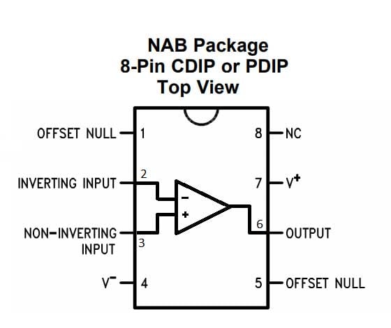
An operational amplifier is a DC-coupled high gain electronic voltage amplifier. It’s a small chip having 8 pins. An operational amplifier IC is used as a comparator which compares the two signal, the inverting and non-inverting signal. In Op-amp IC 741 PIN2 is an inverting input terminal and PIN3 is non-inverting input terminal. The output pin of this IC is PIN6. The main function of this IC is to do mathematical operation in various circuits.
Op-amp basically has Voltage Comparator inside, which has two inputs, one is inverting input and second is non-inverting input. When voltage at non-inverting input (+) is higher than the voltage at inverting input (-), then the output of comparator is High. And if the voltage of inverting input (-) is Higher than non-inverting end (+), then output is LOW. Op-amps have large gain and usually used as Voltage Amplifier. Some Op-amps have more than one comparator inside (op-amp LM358 has two, LM324 has four) and some have just one comparator like LM741.The application of this IC mainly includes an adder, subtractor, voltage follower, integrator and differentiator. The output of the operational amplifier is the product of the gain and the input voltage. Check here for other Op-amp Circuits.
Pin Diagram of Op-amp IC741:
Pin Configuration
|
PIN NO. |
PIN Description |
|
1 |
Offset null |
|
2 |
Inverting (-) input terminal |
|
3 |
non-inverting (+) input terminal |
|
4 |
negative voltage supply (-VCC) |
|
5 |
offset null |
|
6 |
Output voltage pin |
|
7 |
positive voltage supply (+VCC) |
|
8 |
not connected |
Working of Automatic Temperature Controlled Fan using Thermistor
It works on the principle of thermistor. In this circuit, PIN 3 (non-inverting terminal of op amp 741) is connected with the potentiometer and PIN 2 (inverting terminal) is connected in between of R2 and RT1 (thermistor) which is making a voltage divider circuit. Initially, in the normal condition the output of the op amp is LOW as the voltage at non-inverting input is lesser than inverting input which makes the NPN transistor remains in off condition. The transistor remains in OFF condition because there is no voltage applied to its base and we need some voltage at its base to make the NPN transistor conduct. Here we have used NPN transistor MJE3055 but any high current transistor can work here like BD140.
Non when the temperature is increased, the resistance of Thermistor deceases and the voltage at non-inverting terminal of op-amp becomes higher than the inverting terminal, so the op amp output PIN 6 will become HIGH and transistor will be ON (because when the output of op amp is HIGH the voltage will flow through the collector to emitter). Now this conduction of NPN transistor allows the Fan to start. As the thermistor return to the normal condition the fan will automatically turn OFF.
Advantages
- Easy to handle and economical
- Fan starts automatically, so it can control the temperature manually.
- Automatic switching will save the energy.
- For cooling heat dissipating devices, installation is easy.
Applications of Temperature Controlled DC Fan
- Cooling fans for laptops and computers.
- This device is used for cooling the car engine.
Comments
Hi andi,
The LM741 has a Maximum operating voltage of +18V and the MJE3055 Transistor has a Collector current of 10A and base current of 6A. So yes, You should be able to use the same circuit for a 12V source and 12V fan and can also handle current of 1A.
would this be able to drive multiple fans, a bank of 6? thanks.
No it cannot handle that much current for 6 fans. You have to use individual op-amps
What is the watts of the potentiometer, ntc themistor and npn transistor and also the ampere of the power supply?
Will this work using 3 volt supply. I've connected everything up using a 3 volt led and this stays on constantly with no change when I adjust the pot. Thanks
Is there any substitute for NTC Thermistor? Thanks
Yes, there are lots of temperature sensors.... whcih can be used measure temperature LM35 is an example
How to set temperature value at which the fan get started
How to adjust set point temperature value
can I use LM358 instead of LM741 and can I power it using a 12 volt supply?
what will happen in the circuit if we donot use the amplifier
I used this project with IC358 , it is now soldered in the circuit board i made, i also used MJE3055T but it dosent work pls help
thank you, i used this and work like charm but why fan dont work full speed i think problem is from ampere or voltage
can you help me?
ANY DISADVANTAGES?

1.) What if I use 12 volt for the input power and also DC fan that rated 12v? Should I increase/double the amount of resistor and thermistor that has being stated in the schematic? 2.) Is the circuit IC and transistor can handle more than 1 ampere current? Thank you, sir.