

The bistable multivibrator is one of those basic circuits which you might have learnt about in your high school or college, and you probably have built one with 555 timers or with discrete components like OP-amp, transistors, or resistors. These circuits are often viewed as simple educational circuits, but not so surprising they are also used in practical designs even today, for example, check out this electronic missing pulse detector.
In this article, we are going to take the opportunity to design and build a Bistable Multivibrator Circuit with Op-amp, which can change its state depending upon the triggering condition and we are going to finish off this article by making a practical version of our designed circuit and testing it with oscilloscopes. So let’s get right into it. We have also covered basic op-amp circuits like the Summing Amplifier, Differential Amplifier, Instrumentation Amplifier, Voltage Follower, Op-Amp Integrator, etc. You can check those out if you are interested in those topics.
What is Bistable Multivibrator Circuit?
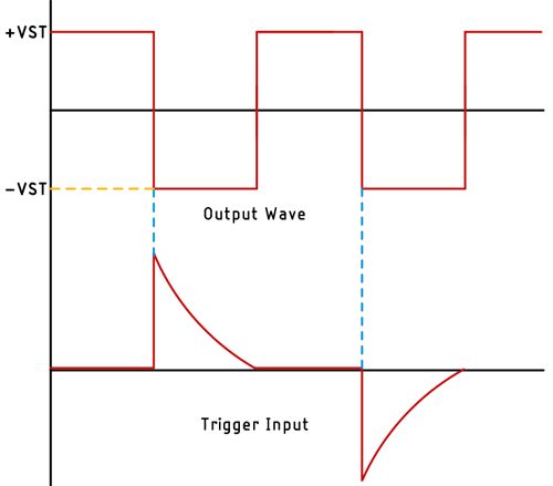
As the name implies, the bistable multivibrator has two stable states, this is why it’s called the bistable multivibrator. This is what you will find in your typical textbook if you go through the topic for a bistable multivibrator circuit. But what does this even mean? It means the output state of this multivibrator circuit will not change until you provide an appropriate trigger pulse. Now when a trigger pulse is applied, the output state of this multivibrator will invert and stay that way until you provide another trigger pulse. The image below will give you a better idea of the process.
This circuit is also referred to as a flip-flop or latch. As we have previously discussed, this circuit has two stable states which is the fundamental property of a latch. Flip-flop and latch are the fundamental building blocks of any digital electronic system and can be used to store information (in a theoretical way).
Understanding a Bistable Multivibrator Circuit with Op-amp
The image below shows a bistable multivibrator with an Op-amp.
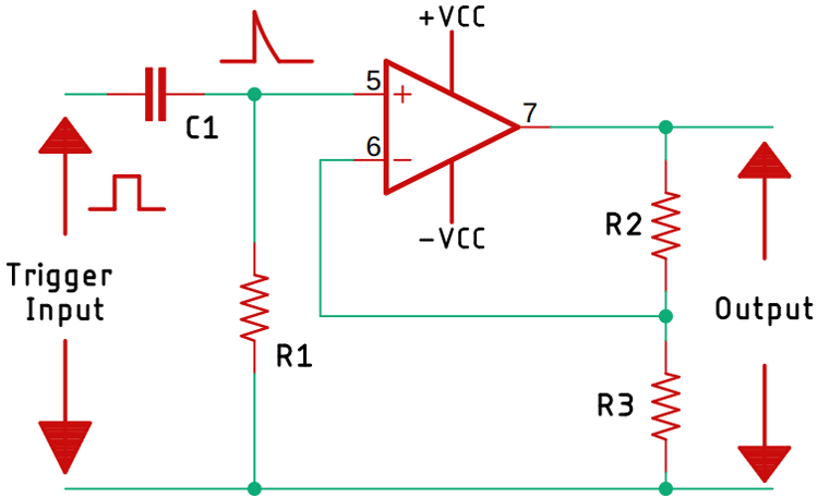
In the above schematic, we have formed a differentiator circuit using C1 and R1. This differentiator circuit is responsible for converting the incoming input pulse into a short spike and it is used to trigger the circuit, but why do we need a differentiator circuit? This is used to alter the saturation state between the two states. In this circuit, we also have to use hysteresis with a Schmitt trigger circuit to prevent noise from triggering the circuit. To understand the working principle of the Schmitt Trigger circuit, you can check out our previous post on Astable Multivibrator Circuit with Op-amp where we have gone through all about Schmitt trigger or else you can check our dedicated article on Schmitt trigger.
The calculation of the bistable multivibrator circuit is very simple. And in this section, we will learn all about it; one thing to keep in mind before proceeding further is that at the time of triggering the circuit, the amplitude of the trigger pulse should be greater than the supply voltage, otherwise the circuit will not get triggered properly and the triggering characteristic also depends upon the Schmitt Trigger circuit. To trigger the circuit, the positive pulse needs to be greater than the positive output voltage through the voltage divider, and similarly, the negative-going pulse needs to be greater as well. We can use the two formulas given below to calculate that.
For a positive trigger, we can use -Vout X R3 / (R2 + R3) and for the negative trigger, we can use +Vout X R3 / (R2 + R3).
Components Required to Build the Bistable Multivibrator Circuit
As the circuit is very simple, the list of required components is very simple too, and you can find most of these components in your local hobby store. To build this circuit, we only need five components, a list of them along with the image is shown below.
- Lm358 Op-amp - 1
- Tactile Switch - 2
- 10K Resistor - 2
- 100R Resistor - 1
- 10nF Capacitor - 1
Op-amp Bistable Multivibrator Circuit
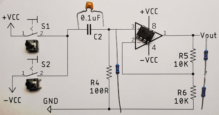
The complete circuit diagram for the Op-amp based Bistable Multivibrator Circuit with values is given below.

In the schematic, you can see we have used two push buttons to trigger the circuit. Button S1 is connected to +VCC and button S2 is connected to -VCC. This is because to change the output state of the Op-amp, we need to trigger the op-amp.
Testing of the Bistable Multivibrator Circuit
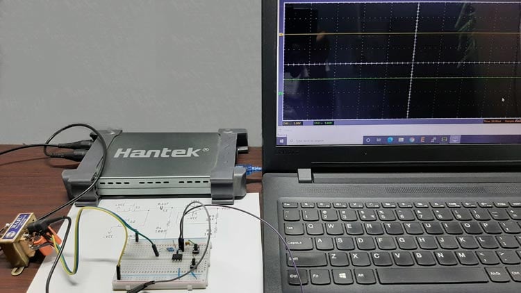
The test setup for the Op-amp based Bistable multivibrator circuit is shown above. As you can see, we have used a transformer with four diodes and two capacitors to produce a dual polarity supply, which is mandatory to power this circuit, also we have used two 10K resistor to configure the circuit as Schmitt trigger. Other than this, we have used one 100R resistor along with a 0.1uF capacitor to build the triggering circuit. Finally, we have connected two push buttons and finished the circuit alongside the LM358 based Op-amp. A close-up image of the circuit is shown below.
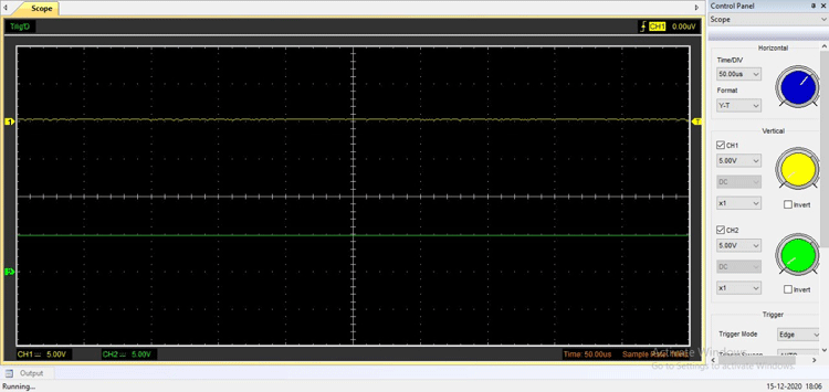
Once the circuit was complete, I pulled out my Hantek oscilloscope and measured the output and it was in the positive saturation region. It looked something like the image below.
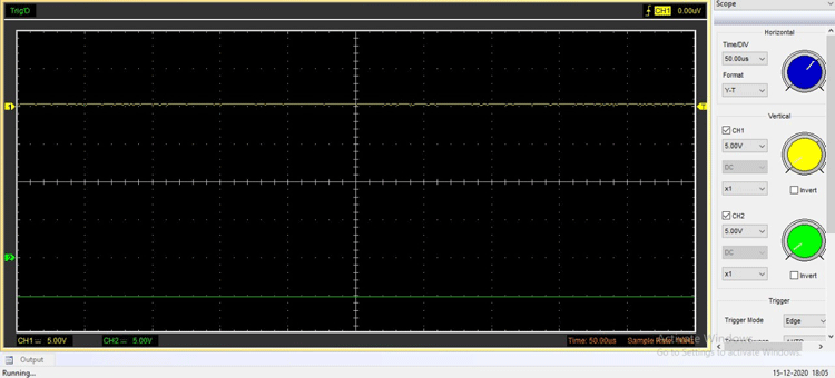
Once that was confirmed, I pushed the negative trigger button and observed that the output switched from the positive saturation region to the negative saturation region. I did this couple of times in order to confirm that the circuit is working properly.
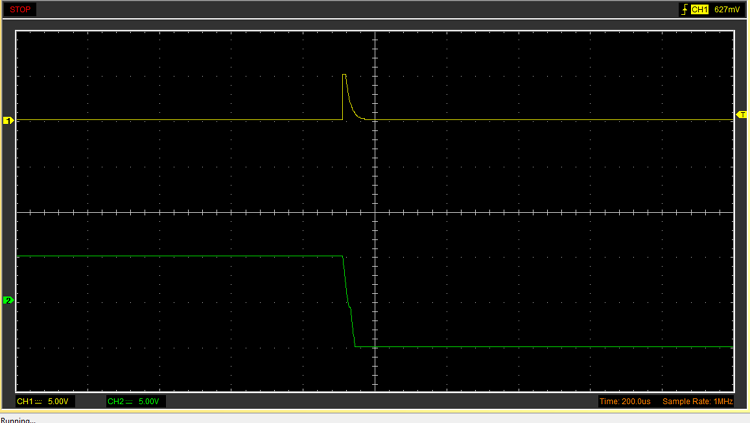
Finally, I put my oscilloscope in the single-shot capture mode and trigger the circuit once again to observe the switching of the output very closely.
This marks the end of this article. I hope you liked the article and learned something new. If you have any questions regarding the article, do not hesitate to comment below, or for a faster response, you can use our electronics forum.

The circuit as shown CAN NOT WORK. There is no Schmitt Trigger. All of the schematics show a non-inverting linear amplifier with a gain of 2. That makes me question the validity of the scope shots.
Consider swapping pins 2 and 3 in all of the schematics. In this way they will agree with the proto-board image in the video.
Also, there is no power supply decoupling.
Also, you have left both of the inputs to the unused opamp section unterminated. This is a very bad design practice, even at the simple prototype level.
ak