

Most of the power supply these days are very reliable due to advancement in technology and better design preferences, but there is always a chance of failure due to a manufacturing defect or it can be the main switching transistor or the MOSFET going bad. Also, there is a possibility that it may fail due to overvoltage at the input, though protection devices like Metal Oxide Varistor (MOVs) can be used as input protection, but once a MOV triggers, it renders the device useless.
To solve this problem, we are going to build an over voltage protection device with an op-amp, which can detect high voltages and can cut of the input power in a fraction of a second protecting the device from a high voltage surge. Also, there will be a detailed test of the circuit to verify our design and working of the circuit. The following examination gives you an idea about the building and testing process for this circuit. If you are into SMPS Design, you can check out our previous articles on SMPS PCB Design Tips and SMPS EMI Reduction Techniques.
What is Overvoltage Protection and Why is It So Important?
There are many ways in which a power supply circuit can fail, one of them is due to overvoltage. In a previous article, we have made an over-voltage protection circuit for the DC circuit, you can check that out if that peaks your interest. Overvoltage protection can be illustrated as a feature where the power supply shuts down when an overvoltage condition occurs, though an overvoltage situation occurs less often, when that happens, it renders the power supply useless. Also, the impact of an overvoltage condition can carry out from the power supply to the main circuit, when that happens, you will end up with not only a broken power supply but also with a broken circuit. which is why an overvoltage protection circuit becomes important in any electronic design.
So, to design a protection circuit for overvoltage situations, we need to clear out the basics of overvoltage protection. In our previous protection circuit tutorials, we have designed many basic protection circuits that can be adapted into your circuit, namely, Over Voltage Protection, Short-Circuit Protection, Reverse polarity protection, Overcurrent Protection, etc.
In this article, we will be concentrating on only one thing, that is to make an input mains overvoltage protection circuit to prevent it from getting destroyed.
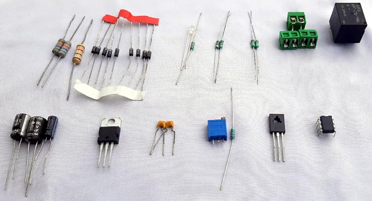
 Components Required
|
Sl.No |
Parts |
Type |
Quantity |
|
1 |
LM358 |
IC |
1 |
|
2 |
BD139 |
Transistor |
1 |
|
3 |
Screw Terminal |
Screw Terminal 5mmx2 |
3 |
|
4 |
1N4007 |
Diode |
9 |
|
5 |
0.1uF |
Capacitor |
2 |
|
6 |
56K,1W |
Resistor |
2 |
|
7 |
1.5K, 1W |
Resistor |
1 |
|
8 |
1K |
Resistor |
2 |
|
9 |
1M |
Resistor |
1 |
|
10 |
560K |
Resistor |
2 |
|
11 |
62K |
Resistor |
1 |
|
12 |
10K |
10 Turns Potentiometer |
1 |
|
11 |
SRD-12VDC-SL-C |
PCB Relay |
1 |
|
12 |
LM7805 |
Voltage Regulator |
1 |
|
13 |
Indicator |
LED |
1 |
|
14 |
Clad Board |
Generic 50x 50mm |
1 |
AC Main Over Voltage Protection Circuit
The complete circuit diagram for our Main Over voltage protection is given below. The working of the circuit is discussed further below.

How 230V Mains Overvoltage Protection Circuit Works?
To understand the basics of the overvoltage protection circuit, let's take the circuit apart in order to understand the basic working principle of every part of the circuit.
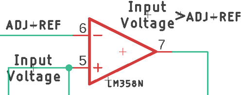
The heart of this circuit is an OP-Amp, which is configured as a comparator. In the schematic, we have a basic LM358 OP-amp and in its Pin-6, we have our reference voltage which is generated from an LM7812 voltage regulator IC and on pin-5, we have our input voltage which is coming from the main supply voltage. In this situation, if the input voltage surpasses the reference voltage, the output of the op-amp will go high, and with that high signal, we can drive a transistor which turns on a relay, but there lies a huge problem in this circuit, Due to noise in the input signal, the Op-amp will oscillate many times before coming to a stable,
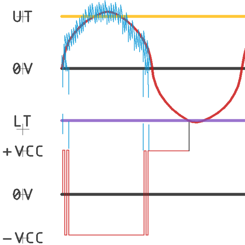
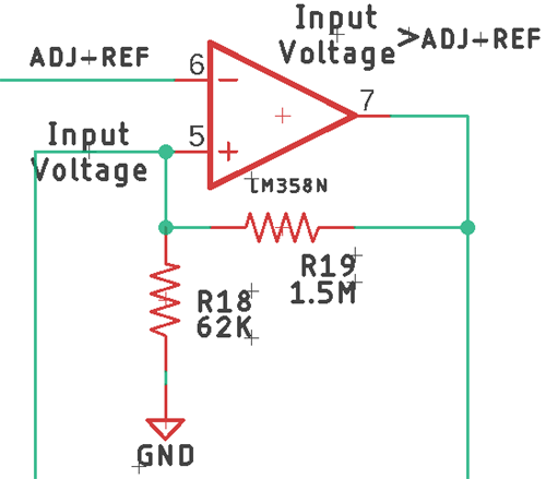
The solution is to add hysteresis of Schmitt trigger action at the input. Previously we have made circuits like Frequency Counter using Arduino and Capacitance Meter using Arduino both of which uses Schmitt trigger inputs, if you want to learn more about these projects, do check those out. By configuring the op-amp with positive feedback, we can widen the margin at the input according to our needs. As you can see in the above image, we have provided feedback with the help of R18 & R19 by doing so, we have practically added two threshold voltages, one is the upper threshold voltage, another is the lower threshold voltage.
Calculating the Component Values for Over Voltage Protection
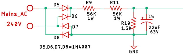
If we look at the schematic, we have our mains input, which we rectify it with the help of a bridge rectifier, then we put it through a voltage divider which is made with R9, R11, and R10, then we filter it through a 22uF 63V capacitor.
After doing the calculation for the voltage divider, we will get an output voltage of 3.17V, now, we need to calculate the upper and lower threshold voltages, Let's say we want to cut power when the input voltage reaches 270V. Now if we do the voltage divider calculation again, we will get an output voltage of 3.56V, which is our upper threshold. Our lower threshold stays at 3.17V as we have grounded the Op-amp.
Now, With the help of a simple voltage divider formula, we can easily calculate the upper and the lower threshold voltages. Taking the schematic as reference the calculation is shown below,
UT = R18 / (R18+R19) * Vout = 62K / (1.5M + 62K) = 0.47V
LT = R18 / (R18+R19) * -Vout = 62K / (1.5M + 62K) = 0V
Now, after the calculation, we can clearly see that we have set your upper threshold voltage at 0.47V above the trigger level with the help of the positive feedback.
Note: Please note that our practical values will differ a bit from our calculated values due to resistor tolerances.
Mains Over Voltage Protection Circuit PCB Design
The PCB for our mains overvoltage protection circuit is designed for a single sideboard. I have used Eagle to design my PCB, but you can use any Design software of your choice. The 2D image of my board design is shown below.

A sufficient trace diameter is used to make the power tracks to flow the current through the circuit board. The AC mains input and the Transformer input section are created on the left-hand side and the output is created on the bottom side for better usability. The complete Design file for Eagle along with the Gerber can be downloaded from the link below.
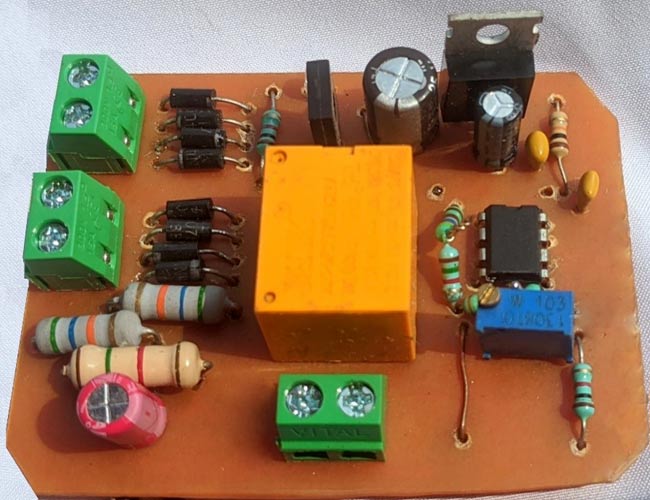
Now, that our Design is ready, it is the time each and solder the board. After the etching, drilling, and soldering process are finished, the board looks like the image shown below.
Testing Over Voltage and Current Protection Circuit
For the demonstration, the following apparatus is used
- Meco 108B+TRMS Multimeter
- Meco 450B+TRMS Multimeter
- Hantek 6022BE Oscilloscope
- 9-0-9 Transformer
- 40W light Bulb (Test Load)
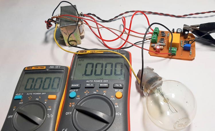
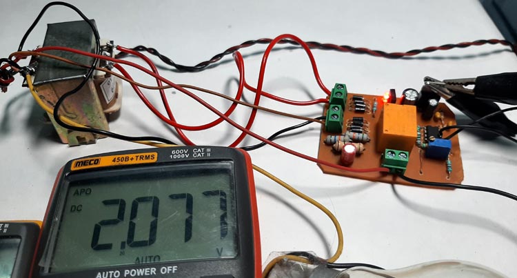
As you can see from the above image, I have prepared this test setup to test this circuit, I have soldered two wires in the pin5 and pin6 of the Op-amp and the meco 108B+ Multimeter is showing the input voltage and the meco 450B+ Multimeter is showing the reference voltage.
In this circuit, the transformer is powered from 230V mains power supply, and from there the power is fed to the rectifier circuit as input, the output from the transformer is also fed into the board as it is providing power and reference voltage to the circuit.
As you can see from the above image, the circuit is on, and the input voltage in the meco 450B+ Multimeter is less than the reference voltage, which means the output is on.
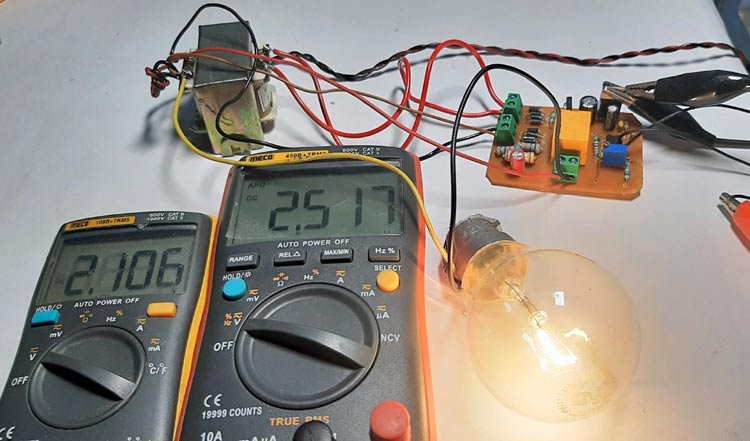
Now to simulate the situation if we reduce the reference voltage, the output will turn off, detecting an over voltage condition, also a red LED on the board will turn on, you can observe that on the image below.
Further Enhancements
For the demonstration, the circuit is constructed on a PCB with the help of the schematic, this circuit can be easily modified to improve its performance, for example, the resistors I have used all have 5% tolerances, using 1% rated resistors can improve the accuracy of the circuit.
Hope you enjoyed the article and learned something useful. If you have any questions, you can leave them in the comment section below or use our forums to post other technical questions.
Comments
Is the speed sufficient to protect the circuit when plugged into a 380v high voltage plug instead of a 230v mains?

I have a question: so many of your circuits use the LM358 as a comparator, which it is not. What is the advantage of using the LM358 dual opamp instead of the LM393 dual comparator (for example)?