

Protection circuits are vital for any electronic design to be successful. In our previous protection circuit tutorials, we have designed many basic protection circuits that can be adapted into your circuit, namely, Over Voltage Protection, Short-Circuit Protection, Reverse polarity protection, etc. Adding to this list of circuits, in this article, we will learn how to design and build a simple Over-current protection circuit using an Op-Amp. In this tutorial, we add to that series by designing a practical overcurrent protection circuit using an op-amp—specifically the popular LM358 overcurrent protection configuration paired with an IRF540N MOSFET for load switching.
An overcurrent protection circuit is essential in power supply design. Overcurrent protection is often used in power supply circuits to limit the output current of a PSU. The term “Overcurrent” is a condition when the load draws a larger current than the specified capabilities of the power supply unit. This can be a dangerous situation, as an overcurrent condition could damage the power supply. So, engineers normally use an overcurrent protection circuit to cut off the load from the power supply during such fault scenarios, thus protecting the load and power supply. The circuit presented here uses an LM358 op-amp configured as a comparator to continuously monitor load current via a shunt resistor and trip a MOSFET overcurrent protection circuit the instant the current exceeds a user-set threshold, with an auto-restart feature built in.
Table of Contents
- What is Overcurrent Protection and Why Does it Matter?
- Overcurrent Protection using Operational Amplifier
- └ Key Components and Pinouts
- Materials Required
- Overcurrent Protection Circuit Diagram
- └ Circuit Block Diagram Overview
- Working
- Dealing with the transient response/stability problem
- Testing
- └ Test Procedure
- Overcurrent Protection Design Tips
What is Overcurrent Protection and Why Does it Matter?
The overcurrent protection circuit described here uses an operational amplifier (op-amp) to monitor the current flowing into a load, and will turn off the load if it exceeds a specified safety threshold. In addition to protecting against excessive current, it also protects the PSU and the load device from overheating, component failure, or other potentially hazardous conditions. This overcurrent protection using op-amp has three distinct advantages over other simpler designs: the ability to adjust the threshold with a trim-potentiometer, to use hysteresis for reliable switching, and to automatically restart once the fault condition has cleared, providing an excellent option for use in power supply applications, motor driver applications, and in systems powered by batteries.
Overcurrent Protection using Operational Amplifier
There are many types of over-current protection circuits; the complexity of the circuit depends on how fast the protection circuit should react during an over-current situation. In this project, we will build a simple over-current protection circuit using an op-amp, which is very commonly used and can be easily adapted for your designs.
Three active components drive this overcurrent protection circuit diagram. Understanding each one's role is essential before building the circuit.
Key Components and Pinouts
The circuit we are about to design will have an adjustable overcurrent threshold value and will also have an Auto-restart on failure feature. As this is an op-amp-based overcurrent protection circuit, it will have an op-amp as the driving unit. For this project, a general-purpose operational amplifier, LM358, is used. In the image below, the pin diagram of the LM358 is shown.
1. LM358 Op-Amp – The Comparator Core
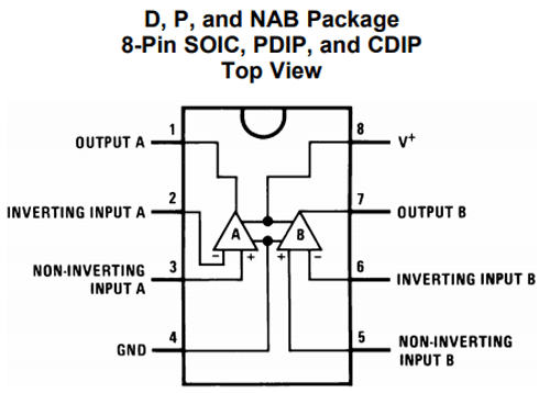
| LM358 Pin | Name | Function in This Circuit |
| 2 (Channel A) | IN− (Inverting) | Senses voltage drop across shunt resistor R1 |
| 3 (Channel A) | IN+ (Non-inverting) | Receives reference voltage from potentiometer RV1 |
| 1 (Channel A) | Output | Drives MOSFET gate through R2; hysteresis via R4 |
| 8 | VCC | Connected to LM7809 regulated 9V output |
| 4 | GND | Common ground |
As seen in the above image, inside a single IC package, we will have two op-amp channels. However, only a single channel is used for this project. The op-amp will switch (disconnect) the output load using a MOSFET. For this project, an N-channel MOSFET IRF540N is used. It is recommended to use a proper MOSFET Heatsink if the load current is larger than 500mA. However, for this project, the MOSFET is used without a Heatsink. The image below is the representation of the IRF540N pinout diagram.
2. IRF540N – The Load-Switching MOSFET
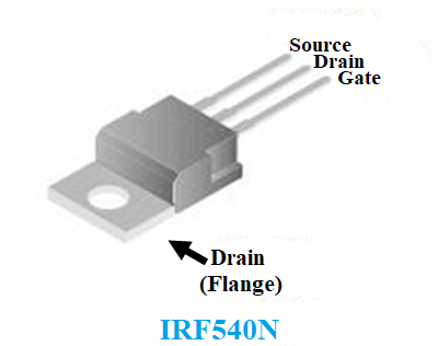
| IRF540N Pin | Connection | Role |
| Gate (G) | Op-amp output via R2 (1kΩ) | Controls ON/OFF state |
| Drain (D) | Load negative terminal | Current flows in (load side) |
| Source (S) | Shunt resistor R1, then to GND | Current flows out to shunt sensing path |
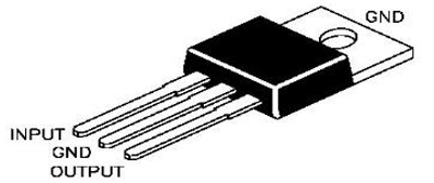
3. LM7809 – Regulated Supply for the Op-Amp
To power the op-amp and the circuitry, the LM7809 linear voltage regulator is used. This is a 9V 1A linear voltage regulator with a wide input voltage rating. The pinout can be seen in the image below
Materials Required for the Overcurrent Protection Circuit
A list of components required for the overcurrent protection circuit is listed below.
| Component | Value / Part No. | Quantity | Purpose |
| Op-Amp IC | LM358 | 1 | Comparator – core of LM358 overcurrent protection |
| N-Channel MOSFET | IRF540N | 1 | Load switching element |
| Voltage Regulator | LM7809 | 1 | Stable 9V supply for op-amp |
| Shunt Resistor | 1Ω, 2W | 1 | Current sensing (R1) — supports up to 1.25A |
| Trim Potentiometer | 50kΩ | 1 | Adjustable reference voltage (RV1) |
| Gate Resistor | 1kΩ, 1% tolerance | 1 | MOSFET gate current limiting (R2) |
| Hysteresis Resistor | 100kΩ, 1% tolerance | 1 | Comparator stability (R4) |
| Gate Pull-Down Resistor | 1MΩ | 1 | Ensures MOSFET turns off fully (R3) |
| Filter Capacitor | 100µF, 25V electrolytic | 1 | LM7809 output noise filtering (C1) |
| Power Supply | 12V DC minimum | 1 | Main supply (must be ≥ LM7809 dropout + 9V) |
| Heatsink | As per load current | 1 | For IRF540N if load > 500mA |
| Breadboard + Wires | – | 1 set | Prototyping |
Overcurrent Protection Circuit Diagram
A simple overcurrent protection circuit diagram can be designed by using an Op-Amp to sense the overcurrent, and based on the result, we can drive a MOSFET to disconnect/connect the load from the power supply. The complete overcurrent protection circuit diagram is shown below.

Circuit Block Diagram Overview
- Input supply (12V+) → LM7809 regulator → 9V stable rail for op-amp and reference divider
- Load path: 12V+ → MOSFET Drain → MOSFET Source → Shunt Resistor R1 → GND
- Sensing path: Voltage across R1 → LM358 inverting input (−)
- Reference path: 9V → 50kΩ potentiometer RV1 wiper → LM358 non-inverting input (+)
- Output path: LM358 output → R2 (1kΩ) → IRF540N gate; R4 (100kΩ) feeds back to IN+
- Gate pull-down: R3 (1MΩ) from gate to GND ensures clean MOSFET turn-off
Overcurrent Protection Circuit Working
Understanding the working of this overcurrent protection using op-amp design requires examining each stage in sequence.
As you can observe from the circuit diagram, the MOSFET IRF540N is used to control the load as ON or OFF during the normal and overload conditions. But before turning off the load, it is essential to detect the load current. This is done by using a shunt resistor R1, which is a 1 Ohm shunt resistor with a 2 Watt rating. This method of measuring current is called Shunt Resistor Current Sensing. You can also check other current sensing methods, which can also be used to detect overcurrent.
During the ON state of the MOSFET, the load current flows through the MOSFET’s drain to source and finally to the GND via the shunt resistor. Depending on the load current, the shunt resistor produces a voltage drop across which can be calculated using Ohm's law. Therefore, let’s assume, for 1A of current flow (load current), the voltage drop across the shunt resistor is 1V as V = I x R (V = 1A x 1 Ohm). So, if this drop voltage is compared with a predefined voltage using an Op-Amp, we can detect overmultiplying current and change the state of the MOSFET to cut off the load.
The operational amplifier is commonly used for performing mathematical operations like adding, subtracting, multiplying, etc. Therefore, in this circuit, the operational amplifier LM358 is configured as a comparator. As per the schematic, the comparator compares two values. The first one is the drop voltage across the shunt resistor, and the other one is the predefined voltage (reference voltage) using a variable resistor or potentiometer RV1. RV1 acts as a voltage divider. The drop voltage across the shunt resistor is sensed by the inverting terminal of the comparator, and it is compared with the voltage reference that is connected to the non-inverting terminal of the operational amplifier.
Due to this, if the sensed voltage is less than the reference voltage, the comparator will produce a positive voltage across the output, which is close to the VCC of the comparator. But, if the sensed voltage is larger than the reference voltage, the comparator will produce a negative supply voltage across the output (negative supply is connected across the GND, so 0V in this case). This voltage is sufficient to switch a MOSFET ON or OFF.
Dealing with the transient response/stability problem
But when the high load is disconnected from the supply, the transient changes will create a linear region across the comparator, and this will create a loop where the comparator couldn't switch the load ON or OFF properly, and the op-amp will become unstable. For example, let’s assume 1A is set using the potentiometer for triggering the MOSFET into the OFF condition. Therefore, the variable resistor is set for a 1V output. During a situation, when the comparator detects the voltage drop across the shunt resistor is 1.01V (this voltage depends on the op-amp or comparator accuracy and other factors), the comparator will disconnect the load. Transient changes occur when a high load is suddenly disconnected from the power supply unit, and this transient increases the voltage reference, which invites poor results across the comparator and forces it to operate in a linear region.
The best way to overcome this problem is to use a stable power across the comparator, where the transient changes do not affect the comparator’s input voltage and the voltage reference. Not only this, but an additional method of hysteresis needs to be added in the comparator. In this circuit, this is done by the linear regulator LM7809 and by using a hysteresis resistor R4, a 100k resistor. LM7809 provides a proper voltage across the comparator so that the transient changes across the power line do not affect the comparator. C1, the 100uF capacitor is used for filtering the output voltage.
The hysteresis resistor R4 feed a small portion of the input across the output of the op-amp, which creates a voltage gap between the low threshold (0.99V) and the high threshold (1.01V) where the comparator changes its output state. The comparator does not change the state immediately if the threshold point is met, instead of that, to change the state from high to low, the sensed voltage level needs to be lower than the low threshold (for example 0.97V instead of 0.99V) or to change the state from low to high, the sensed voltage needs to be higher than the high threshold (1.03 instead of 1.01). This will increase the stability of the comparator and reduce false tripping. Other than this resistor, R2 and R3 are used for controlling the gate. R3 is the Gate pull-down resistor of the MOSFET.
Overcurrent Protection Circuit Testing
The circuit is constructed in a breadboard and tested using a bench power supply along with a variable DC Load.
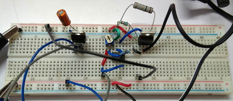
The circuit is tested, and the output was observed to successfully get disconnected at different values set by the variable resistor. The video provided at the bottom of this page shows a complete demonstration of overcurrent protection testing in action.
Test Procedure
The following steps should be followed during testing:
- The RV1 potentiometer must be set to the correct current threshold (using a multimeter), so monitor the wiper voltage) (example: If your setting is 1.0 volts, you will trigger at one amp).
- Hook up the load to the circuit running off a 12V power supply.
- Gradually increase the current through the load using your variable DC load.
- As you increase the load current, observe that when the shunt voltage exceeds Vref (reference voltage), the MOSFET will see a gate voltage drop (0V).
- Decrease the load current to see if it auto-restores and reconnects to the load.
- Repeat this for multiple trip threshold settings to determine how linearly the trip point responds.
Overcurrent Protection Design Tips
Based on hands-on experience with this and similar protection circuit designs, here are actionable tips for improving performance in real-world applications:
- RC snubber circuit across the output could improve the EMI.
- A larger heat sink and a specific MOSFET can be used for the required application.
- A well-constructed PCB will improve the stability of the circuit.
- The Shunt Resistor wattage needs to be adjusted as per the power law (P = I2R), depending on the Load Current.
- A very low-value resistor in milli-ohms rating can be used for a small package, but the voltage drop will be less. To compensate for the voltage drop, an additional amplifier with proper gain can be used.
- It is advisable to use a dedicated current sense amplifier for accurate current sensing related issues.
| Design Consideration | Recommendation | Benefit |
| Shunt Resistor Wattage | Use P = I²R and select a resistor rated at 2× calculated dissipation | Prevents resistor failure and thermal drift at high currents |
| Low-value Shunt (mΩ range) | Pair with a dedicated current sense amplifier (INA219, INA240) | Reduces I²R losses; enables accurate sensing at high currents (>2A) |
| MOSFET Selection | Choose MOSFET with RDS(on) appropriate for load current | Lower conduction losses; less heatsinking required |
| MOSFET Heatsink | Add heatsink for load currents above 500mA | Prevents thermal shutdown or MOSFET destruction |
| PCB Layout | Keep shunt resistor traces short and wide; use Kelvin (4-wire) sensing for accuracy | Eliminates PCB trace resistance error in current measurement |
| RC Snubber | Place RC snubber across the load output to suppress switching transients | Reduces EMI; protects MOSFET from inductive load voltage spikes |
| Op-Amp Alternative | Use a dedicated comparator IC (LM393) for faster response (<1µs) | Better for high-speed short circuit protection applications |
| 1% Tolerance Resistors | Use 1% tolerance for R2, R3, R4 and the RV1 voltage divider | Ensures accurate and repeatable current threshold calibration |
Hope you understood the tutorial and enjoyed learning something useful from it. If you have any questions, please leave them in the comment sections or use the forums for other technical questions.
Frequently Asked Questions - Overcurrent Protection Circuit
⇥ For what reason is an overcurrent protection shunt resistor utilized?
A Shunt Resistor transforms load current into a proportional measurable voltage (V=IR) to comply with Ohm's law; this voltage is sent directly into an Op Amp comparator as its input for sensing purposes. The shunt value and wattage rating must be calculated using P=I²R so that the resistor will not overheat or fail during maximum load current conditions.
⇥ In this circuit, R4 (the hysteresis Resistor) serves what purpose?
The 100kΩ Hysteresis Resistor R4 provides feedback of a portion of the OP AMPS Output to its non-inverting (+) input; thereby creating positive feedback to establish a gap between the trip threshold voltage and the reset threshold voltage; this will help to stabilize operation of the comparator and prevent rapid oscillation/chattering around the defined overcurrent trip set-point and, will also provide clean stable MOSFET Switching.
⇥ Why utilize LM7809 as opposed to taking power directly from the primary supply?
The LM7809 provides a transient-free and regulated +9Vdc supply to the LM358 and to the RV1 reference divider; there would be significant voltage spikes on the primary rail created when loads are abruptly disconnected, thus shifting the reference voltage of the comparator (causing false trip signals or erratic switching); therefore the regulated rail offers no possibility of this instability occurring.
⇥ Is there any other IC that I can use to replace the LM358?
There are several other op amps or comparators that could potentially be used to replace an LM358 in this overcurrent application. Some examples might be LM741, TL071, TL072, or the UA741. Alternatively, you could replace the LM358 with a different comparator such as LM393 or LM311 which would allow a faster response time (< 1µs). The LM358 is preferred because it works with single supply voltage, has a low input offset voltage, and is amongst the lowest priced op-amps for general use.
⇥ What MOSFETs can replace the IRF540N in this Overcurrent Protection Configuration?
Basically any N-channel power MOSFET that works with your op-amp gate drive voltage will work to replace the IRF540N. Three commonly used options include: IRFZ44N; (49A/55V); STP55NF06; (55A/60V); and FQP30N06L; (32A/60V). If you are using a high side switching configuration, you might want to look at P-channel MOSFETs and their appropriately rated gate drivers. Please remember to add a heat sink when using currents greater than 500mA.
⇥ What is the difference between overcurrent protection and short circuit protection?
Overcurrent protection is designed to handle slowly increasing excess current (such as a motor overload or having too many loads operating in parallel) and will generally react in milliseconds. Short circuit protection, on the other hand, must react in microseconds to a fault condition (essentially to a very low impedance). An op-amp comparator circuit effectively handles slow, gradual overload conditions. However, true short-circuit protection generally requires fast acting fuses, dedicated ICs or crowbar-type circuits with a response time of less than 10μs.
⇥ How does auto-restart function in this overcurrent protection circuit?
When the MOSFET is turned OFF due to an overcurrent condition, the load current has dropped to 0 which eliminates the voltage drop across R1. This pulls down the inverting input of op-amp below the lower hysteresis threshold causing the op-amp to return back to its high output state enabling the turn ON of the MOSFET. If the fault has been cleared then normal operation will resume. If the fault continues, the circuit will continue in its trip-to-off-to-trip loop until the fault clears.
This overcurrent protection circuit using op-amp design, built around the LM358 overcurrent protection configuration with an IRF540N MOSFET, LM7809 regulator, and a 1Ω shunt resistor,delivers a reliable, adjustable, and auto-restarting solution suitable for PSU designs, motor controllers, and battery management systems. Hope you understood the tutorial and enjoyed learning something useful from it. If you have any questions, please leave them in the comment sections or use the forum for other technical questions.
Power Protection Circuit Projects
A collection of simple circuits focused on protecting electronic systems and battery setups from faults like overvoltage, overcurrent, reverse polarity, and inrush current. These projects demonstrate practical methods to improve safety, reliability, and lifespan of electronic devices.

230V AC Mains Over Voltage Protection Circuit
The detailed test of the circuit to verify our design and working of the circuit. The following examination gives you an idea about the building and testing process for this circuit.

Designing a Simple 12V Li-Ion Battery Pack with Protection Circuit
how to design a simple 12V Li-Ion battery pack and how to use it with a protection circuit. A lithum-Ion battery is one of the most commonly used energy storage devices employed for powering equipment and gadgets in today’s time.

Inrush Current – Causes, Effects, Protection Circuits and Design Techniques
In this article we will discuss how to design an inrush current limiter circuits, to protect your Power supply designs from inrush currents. We will first understand what inrush current is and the reason why it is generated.
