

Candles have been of great use since ages, it has been guiding humans during night even before Edison came up with the idea for bulbs. Today, from Churches to kitchens, Candles are used not only to provide light when needed but also adds up to the aesthetics and provides a warm feeling. While ordinary candles work fine, they melt away pretty fast making the place nasty and at times if unattended, it can also lead to fire hazards. So, in this tutorial we are going to make flameless electronic candle by using some simple electronics and an LED. Further this Smart Candle will turn on automatically in night or during darkness and will shut itself off during the day time. It has the same concept which we have previously used in many darkness detector circuits:
- Dark and Light Indicator Circuit
- Dark Detector using LDR and 555 Timer IC
- Simple Keyhole Lighting Device Circuit
- Automatic Staircase Light
Materials Required
- LM358 IC
- LDR (Photo resistor)
- 1M and 1K resistor
- LEDs
- 10K Pot
- 12V Female DC Power Jack and 12V Adapter
- Card sheet and Perfboard
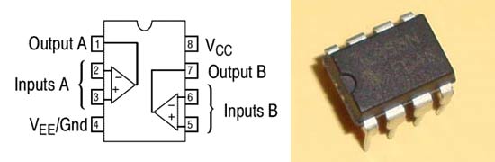
LM358 – Op-Amp Comparator
The brain behind this circuit is the LM358 IC which acts as a comparator in this particular design. Let’s look into it briefly before we dive deeper. The LM358 is an operational amplifier (Op Amp) IC. This IC consist two operational amplifiers which can bear a voltage between 3.3V to 32V and it has a really low supply current drain of 500μA. The IC looks internally like the image below:
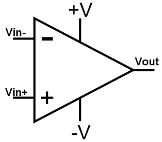
It is generally used in building simple comparator and amplifier circuits and can also be found in active filter circuits, wave shapers etc, in this project we will using LM358 as voltage comparator. A voltage comparator is used to compare two voltages and find out which is greater than the other and then turn the output high or low depending on that. So, if we apply voltage to inverting and non-inverting inputs and if the voltage on non-inverting input is greater than the voltage on inverting input then, the output goes high and if vice versa the output goes low. This project works entirely on this principle. The formula for voltage comparison is given as:
VOUT=AO(Vin+ - Vin-)
Where AO is the open loop gain of op amp. Vin+ is the input voltage at non inverting input terminal and Vin- is the input voltage at inverting input terminal. So, if Vin+ is greater than Vin- then the output will be high else it will be low.
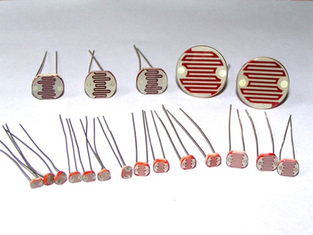
LDR
If the Op-amp is the brain of our circuit, then LDR is the sensory organ. Light Dependent Resistor (LDR) or Photo resistor is a light controlled resistor. Its resistance decreases with increase in light intensity and vice versa. Actually, when light is incident on the LDR then the semiconductor absorbs the photons of light and the bonded electrons jump to conduction band and the resistance decreases due to photoconduction. To know more about LDR and its working, follow the link.
Circuit Diagram and Explanation
The circuit is not really hard; the complete circuit diagram for Electronic Candle is given below.

As shown in the circuit diagram, connect a 1K resistor to pin 1 of the IC and then connect positive end of an LED to this resistor and negative to the ground. Now connect the middle pin of 10K pot to the pin 2 of the IC and connect ground and 12V to the rest of the pot’s pins. Connect a 1M resistor to 12V and connect LDR in series with this resistor. Now, connect the other end of LDR to ground of the circuit. Connect the common point of the LDR and 1M resistor with pin 3 of IC. Connect 12V to pin 8 and ground to pin 4 of IC and you are ready. You don’t need to be very selective about the resistors, we have connected. But make sure that the resistor connected to LDR is in mega ohms and the resistor with LED is in few thousands.
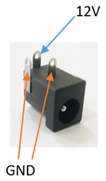
We have built the complete circuit on a dotted board to make it compact and easy to use. It is really a simple circuit, you just need to brush up your soldering skills and start designing it. Firstly, mount the 12V female DC power jack on the perfboard. Remember the pin configuration of this jack while designing the circuit. It is shown in the figure below:
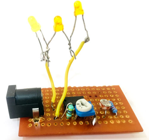
The pinouts of op-amp is already discussed above and resistors and LDRs do not have polarity. Once your soldering work is complete, the board should look something like this shown in the picture below.
Smart Electric Candle - Working
After designing the circuit on the perfboard and soldering it up, connect the 12V adapter to the female jack and your LED must be glowing. Now, to calibrate the comparator adjust the 10K pot to the level where the LED just turns off. Now cover the LDR with your hand and you’ll see the LED turning ON. You can adjust the sensitivity of the LDR by adjusting the pot.
Now, let us understand how this candle works. As we already know that in darkness the resistance of the LDR increases to mega ohms and it decreases with increase in intensity of light to few hundred ohms. So in the light as the resistance is very low so, the voltage across non-inverting signal is very low as compared to the inverting terminal because of the 10K pot we have connected. So in this case the output voltage is also low hence the LED does not turn ON. But in case of darkness the resistance increases to mega ohms, which is quiet high in comparison to the 10K pot, hence the LED glows up.
Adjusting the pot will manipulate the sensitivity. By sensitivity, I mean at what intensity of light your comparator turns on the LED. If you adjust the pot close to the LED turning on, then it will detect minute darkness too. But if you adjust it far before the LED turns ON, then it will only be able to detect high darkness. You can also test the sensitivity by bringing your hand in front of the LDR. It is highly sensitive if it detects your hand far away and it is less sensitive if you need to cover it up to glow the LED.
If you want to use more than one LEDs then it’s not an issue. Connect two-three LED’s in series and finally connect them where we were connecting a single LED and its perfecto. But make sure your comparator could source enough current to power all the LEDs.
To make the candle, you can use anything to cover the LED. I’ve used a card sheet and a tissue. Roll the card sheet according to the size of LED and cut it from above a little in shape of a flame or in any shape you want, so that it can look attractive. Cover up the LED with this candle and you’ve made your own Smart Electronic Candle.
I’ve also simulated this circuit on proteus 8. You can also design it by your own. Just follow the circuit diagram above and set the light intensity of LDR to 1000 and start lowering it up until it becomes zero and you will see the LED glowing up as shown in the video below.

What adjustments would be required to run this from a lithium battery or two instead of 12 volts?