
We are going to build a simple Light Sensing circuit or Light Detector using LDR - a resistive light sensor, to control the ON-OFF of the system associated with respect to the intensity of light that falls on it.
Components Required:
- LDR (Light Dependent Resistor)
- BC547 Transistor
- LED
- Battery 9V DC
- Potentiometer (5KΩ)
- Resistor (1KΩ)
- Connecting Wire
- Breadboard
LDR (Light Dependent Resistor):
There are many photosensors but a very common, inexpensive and easy to use one is LDR which works effectively even in rough conditions.
LDR is also known as Photo resistor as its resistance varies with variation of photons or light falling on it, in lamen term. LDR are mostly made by using a cadmium sulfide (CdS) which is a semiconductor material. As seen in the image below, LDR is a two terminal device with zig-zag trails from one end to another. It has an isolation layer above below there is CdS.
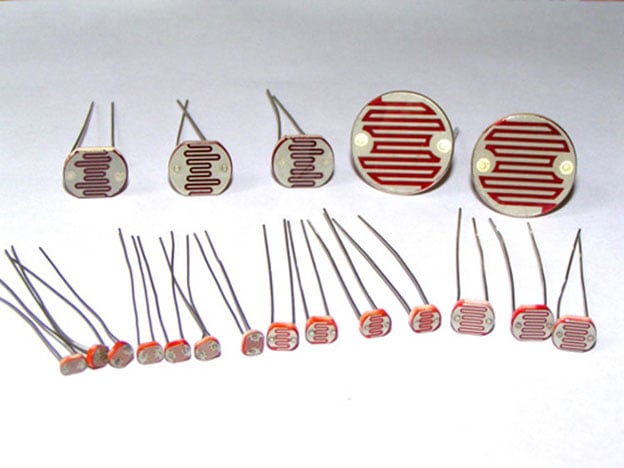
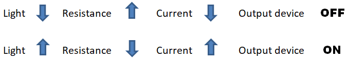
In dark, the resistance of LDR is very high in range of MΩ which decreases when exposed to light. The LDR symbol and its pictorial relationship with light and resistance is shown below.

Light Detector Sensor Circuit Diagram:

The circuit of light detector is very simple and easy to build with very few components. As you can see in the LDR circuit diagram, it can be a distinguished as two smaller circuits; a) Voltage divider made using LDR (LDR1) and a Potentiometer (RV1) b) Output (LED D1) in our switching circuit made using a transistor BC547 Q1.
Voltage divider circuit will divide the total VCC=9V DC into two set of voltage level using two set of resistors, making it possible to give some portion of the total input to the output. In our case voltage across RV1 will be given to the transistor Q1.
Let us understand Part a) Voltage divider and its simple calculation:
The general formula for calculating voltage divider output VO with resistor R1 and R2 and input VIN :-
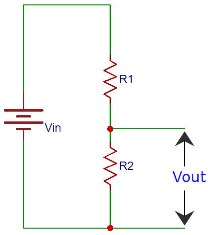
To calculate Vo (VR2) we have to consider R2 divided by the sum of the two resistors R1 and R2 multiplied by the total input voltage VIN;
Vo = [R2 / (R1 + R2)] ×VIN
Similarly, in our circuit we need to calculate o/p voltage of the voltage divider i.e. VRV1,
VRV1 = [RV1 / (RV1 +R LDR1)] × VIN
The above formula can be used for fixed value accurately.
However in our case, when the light is detected by the LDR and LED is ON, following is the result:
VIN = 9V, RV1 =1kΩ (pot position), VRV1=0.7 V; R LDR1 = 11857 Ω(≈11k Ω -12k Ω)
Here we had used a variable resistor RV2 as to select the sensitivity of the LDR to turn OFF in the dark, that is we can select how fast or at what intensity of light should the LED be switched OFF. This a very efficient way and lot of our need and purpose of light can be achieved by the use of variable pot. The pot gives us flexibility to decide the threshold voltage according to different applications.
Part b) is a simple transistor switching ON/OFF circuit. As we know BC547 transistor switched ON when its base to emitter voltage ≥0.7 V and will be OFF if <0.7 V.
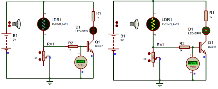
The above image shows the simulation of this LDR circuit, when there is dark the LED remains off and when there is light, the LED turns on.
