

In 1980, Intel developed the first Microcontroller (8051) with Harvard Architecture 8051 and since then Microcontrollers brought a revolution in Electronics and embedded industry. And with the technological advancement over the time, now we have many more efficient and low power microcontrollers like AVR, PIC, ARM. These Microcontrollers are more capable and easy to use, having the latest communication protocols like USB, I2C, SPI, CAN etc. Even Arduino and Raspberry Pi have completely changed the perspective towards Microcontrollers, and Raspberry Pi is not just a microcontroller but it has whole computer inside.
This will be the first part of a series of tutorials that are yet to come, which will help you in learning PIC Microcontrollers. If you are from a electronics background and you always wanted to start with learning some Microcontrollers and get yourself into the world of coding and building stuff, then this series of tutorials will be your first step to begin with.
I am also updating this article with the list of tutorials in ascending order below so that you can select the one you wish to read next
- Getting started with PIC Microcontroller: Introduction to PIC and MPLABX
- Writing Your First Program with PIC Microcontroller and Setting up Configuration Bits
- LED Blinking with PIC Microcontroller
- LED Blinking Sequence using PIC Microcontroller
- Understanding Timers in PIC Microcontroller with LED Blinking Sequence
- LCD Interfacing with PIC Microcontroller using MPLABX and XC8
- Display Custom Characters on 16x2 LCD using PIC Microcontroller and XC8
- 7 Segment Display Interfacing with PIC Microcontroller
- Using ADC Module of PIC Microcontroller with MPLAB and XC8
- Generating PWM using PIC Microcontroller with MPLAB and XC8
- Interfacing Servo Motor with PIC Microcontroller using MPLAB and XC8
- UART Communication using PIC Microcontroller
- Interfacing Bluetooth Module HC-06 with PIC Microcontroller
- Interfacing ESP8266 with PIC16F877A Microcontroller
- How to Send E-mail using PIC Microcontroller and ESP8266
- How to Save Data using EEPROM in PIC16F877A Microcontroller
- How to Use Interrupts in PIC16F877A Microcontroller
- GSM module Interfacing with PIC Microcontroller - Make and Receive Calls
- SPI communication with PIC
- I2C communication with PIC
PIC microcontroller is very convenient choice to get started with a microcontroller projects, because it has excellent support forums and will act as a strong base to build upon all your advanced Microcontrollers that you are yet to learn.
These tutorials are made for absolute or intermediate Learners; we have planned to start with the most basic projects to the advanced ones. We expect no pre-requisites from the learners as we are here to help you out from any level. Every tutorial will have a theoretical explanation and simulation followed by a hands-on tutorial. These tutorials will not involve any development boards, we will make our own circuits using a perf board. So gear up, and make some time every week to enhance you with Microcontrollers.
Now let's get started with a Simple Introduction on PIC Microcontrollers and some software setups to get us running on our next tutorial. Check the Video at the end for installing and setup the MPLABX, XC8, Proteus and a quick unboxing of PICkit 3 programmer.
PIC Microcontroller Architecture and Applications:
The PIC microcontroller was introduced by Microchip Technologies in the year 1993. Originally these PIC were developed to be a part of PDP (Programmed Data Processor) Computers and each peripheral devices of the computer were interfaced using this PIC microcontroller. Hence the PIC gets its name as for Peripheral Interface Controller. Later Microchip has developed a lot of PIC series IC's which can be used for any small application like a lighting application till the advanced one.
Every Microcontroller is to be build around some architecture, the most famous type of Architecture is the Harvard architecture, our PIC is based on this architecture as it belongs to the classic 8051 family. Let's get into a small intro about the Harvard architecture of the PIC.
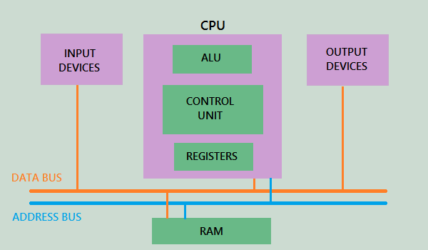
The PIC16F877A Microcontroller consists of an inbuilt CPU, I/O ports, memory organization, A/D converter, timers/counters, interrupts, serial communication, oscillator and CCP module which to gather makes the IC a powerful microcontroller for beginners to start with. The general block diagram of the PIC Architecture is shown below
CPU (Central Processing Unit):
The microcontroller has a CPU to perform Arithmetic operations, Logical decisions and Memory related operations. The CPU has to co-ordinate between the RAM and the other peripherals of the Microcontroller.
It consists of an ALU (Arithmetic Logic Unit), using which it performs the arithmetic operations and logical decisions. A MU (Memory unit) is also present to store the instructions after they get executed. This MU decides the program size of our MC. It also consists of a CU (Control Unit) which acts as a communication bus between the CPU and other peripherals of the microcontroller. This helps in fetching the data after it gets processed in the specified registers.
Random Access Memory (RAM):
A Random Access memory is the one which decides the speed of our microcontroller. The RAM consists of register banks within it, each of which is assigned a specific task. On the whole they can be classified into two types:
- General Purpose Register (GPR)
- Special Function Register (SFR)
As the name suggests the GPR are used for general register functions like addition, subtraction etc. These operations are limited within 8-bit. All the registers under the GPR are user writable and readable. They do not have any functions on their own unless it is software specified.
Whereas the SFR is used to perform complicated special functions which also involves some 16-bit handling, their registers can only be read (R) and we cannot write (W) anything to them. So these registers have a predefined functions to perform, which are set at the time of manufacturing and they just display the result to us, using which we can perform some related operations.
Read Only Memory (ROM):
Read only memory is the place where our program gets stored. This decides the maximum size of our program; hence it is also called as program memory. When the MCU is under operation, the program stored in the ROM is executed as per each instruction cycle. This memory unit can be used only while programming the PIC, during execution it becomes a read only memory.
Electrically Erasable Programmable Read Only Memory (EEPROM):
EEPROM is another type of Memory Unit. In this memory unit values can be stored during program execution. The values stored here are only Electrically Erasable that is these values will be retained in the PIC even when the IC is turned off. They can be used as small memory space to store the executed values; however the memory space will be very less in turns of KB.
Flash Memory:
Flash memory is also Programmable Read Only Memory (PROM) in which we can read, write and erase the program thousands of times. Generally, the PIC microcontroller uses this type of ROM.
I/O Ports
- Our PIC16F877A consists of five ports namely Port A, Port B, Port C, Port D & Port E.
- Of all the five PORTS only Port A is 16-bit, and PORT E is 3-bit. The rest of the PORTS are 8-bit.
- The pins on these PORTS can be used as either Input or Output, based on the TRIS Register configuration.
- Apart from performing I/O operations the pins can also be used for Special functions like SPI, Interrupt, PWM etc.
Bus:
The term Bus is just a bunch of wires that connects the Input or Output Device with CPU and RAM.
Data bus is used to transfer or receives the data.
Address bus is used to transmit the memory address from the peripherals to the CPU. I/O pins are used to interface the external peripherals; UART and USART both serial communication protocols are used for interfacing serial devices like GSM, GPS, Bluetooth, IR , etc.
Selection of PIC Microcontroller for Our Tutorials:
PIC Microcontrollers from Microchip Company are divided into 4 large families. Each family has a variety of components that provide built-in special features:
- The first family, PIC10 (10FXXX) - is called Low End.
- The second family, PIC12 (PIC12FXXX) – is called Mid-Range.
- The third family is PIC16 (16FXXX).
- The fourth family is PIC 17/18(18FXXX)
Since we are starting to learn about PIC, let us select an IC which is used and available universally. This IC belongs to the 16F family the part number of the IC is PIC16F877A. From the first tutorial till the end we will be using the same IC as this IC is equipped with all advanced features like SPI, I2C, and UART etc. But if you don't get any of these things now it's completely fine, we will get progressed through every tutorial and finally uses all the above mentioned features.
Once the IC is selected, it is highly important to read the datasheet of the IC. This should be the first step in whatever concept that we are about to try. Now since we have selected this PIC16F877A lets read through the specification of this IC in the Datasheet.
The Peripheral Feature, mentions that it has 3 Timers, two of which are 8-bit and one is 16-bit prescaler. These Timers are used to create timing functions in our program. They can also be used as counters. It also shows that it has CCP (Capture Compare and PWM) options, which helps us to generate PWM signals and read the incoming frequency signals. For communication with external device, it has SPI, I2C, PSP and USART. For safety purpose it is equipped with Brown-out Reset (BOR), which helps in resetting the while program.
The Analog Features, Indicates that the IC has 10-bit 8-channel ADC. This means, our IC can convert Analog values to digital with a resolution of 10-bit, and has 8 analog pins to read them. We also have two internal comparators that can be used to compare the incoming voltage directly without actually reading them through the software.
The Special Microcontroller Features, signifies that it has 100,000 erase/write cycle, meaning you can program it for about 100,000 times. In-Circuit Serial Programming™ (ICSP™), helps us to program the IC directly using PICKIT3. Debugging can be made via In-Circuit Debug (ICD). Another safety feature is the Watchdog Timer (WDT), which is a self reliable timer that resets the whole program if required.
The below image represents the pinouts of our PIC16F877A IC. This image represents each pin against its name and its others features. This can also be found in the datasheet. Keep this image handy for it will help us during our hardware works.

Selection of Software for Our Tutorials:
PIC microcontroller can be programmed with different software's that is available in the market. There are people who still use Assembly language to program PIC MCUs. For our tutorials we have selected the most advanced software and compiler that have been developed by Microchip itself.
In order to program the PIC microcontroller we will need an IDE (Integrated Development Environment), where the programming takes place. A compiler, where our program gets converted into MCU readable form called HEX files. An IPE (Integrated Programming Environment), which is used to dump our hex file into our PIC MCUs.
IDE: MPLABX v3.35
IPE: MPLAB IPE v3.35
Compiler: XC8
Microchip has given all these three software for free. They can be downloaded directly from their official page. I have also provided the link for your convenience. Once downloaded install them on your computer. If you have any problem doing so you can view the Video given at the end.
For Simulation purpose we have used software called PROTEUS 8, provided by Labcenter. This software can be used to simulate our code generated using the MPLABX. There is a free demonstration software which can be downloaded from their official page through the link.
Getting Ready with Hardware:
All our tutorials will end up with hardware. To learn PIC in the best way possible it is always recommended to test our codes and circuits over hardware, because the reliability of the simulation is very less. Codes which work on a simulation software, might not work as you expected on your hardware. Hence we will be building our own circuits on a Perf boards to dump our codes.
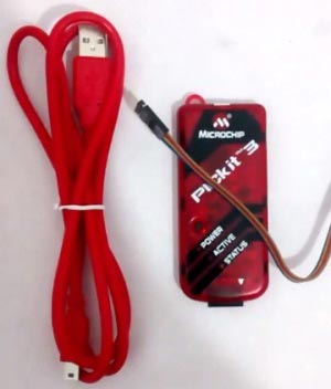
To dump or upload our code into PIC, we will need PICkit 3. The PICkit 3 programmer/debugger is a simple, low-cost in-circuit debugger that is controlled by a PC running MPLAB IDE (v8.20 or greater) software on a Windows platform. The PICkit 3 programmer/debugger is an integral part of the development engineer's tool suite. In addition to this we will also need other hardware like Perf board, Soldering station, PIC ICs, Crystal oscillators, capacitors etc. But we will add them to our list as we progress through our tutorials.
I brought my PICkit 3 from amazon, the unboxing video of the same can be found in the video below. The link for PICKIT3 is also provided; the price may be a bit high but trust me it is worth investing.
NOW WITH ALL THE THINGS READY WE WILL START WORKING FROM OUR NEXT TUTORIAL
Comments
Hi Milind,
Please stick on to the tutorials, we will defiantly meet your demands. We can help you better if you can provide us the materials you have used for single dot matrix.
I have a pic 16f877a and icd 3 , I just want to know if the same procedure could be followed ?
Hi Neeraja,
Yes you can use an ICD 3 instead of Pickit 3. The thing that will change is, while setting up a new project you have to select ICD 3 in the select tool window. If you find any difficulty please feel free to use the forum.
As shown in step four of this tutorial: https://circuitdigest.com/microcontroller-projects/writing-your-first-p…;
HAPPY PROGRAMMING!!
Hi Aswinth, may I use K150 ICSP programmer instead of Pickit 3?
Hi Richo,
Yes you can use K150 ICSP programmer instead of PicKit3. But it has few shortcomings as mentioned below.
1. You will only be able to program the PIC MCU, in future if you want to debug you PIC MCU this programmer will not support you
2. It will not support all pic MCU,s. In this tutorial we use PIC16F877A, so it will not be a problem. But in future if you want to use some new MCU this programmer will not support you.
Thanks,
Aswinth Raj
May I use the PICkit2 instead of the Pickit3? It's the only one I have and the PicKit3 is really expensive.
I thank you in advance.
For all my tutorials in you can also use pickit2 instead of pickit3. Since MPLABX does not allow pickit2 programming you have to download a software called pickit2. Follow the link to download the software. Then you have to simply load the hex file select you MCU as PIC16F877A and upload your program.
PICkit 2 V2.60 Install
PICkit 2 V2.60 Install with .NET Framework
ALL THE BEST!
How do I access the rest of the tutorials please?
KR
I am posting the links of tutorials in a logical sequential manner below so that it would be easy for learns to learn them one by one.
- Getting started with PIC Microcontroller: Introduction to PIC and MPLABX
- Writing Your First Program with PIC Microcontroller and Setting up Configuration Bits
- LED Blinking with PIC Microcontroller
- LED Blinking Sequence using PIC Microcontroller
- Understanding Timers in PIC Microcontroller with LED Blinking Sequence
- LCD Interfacing with PIC Microcontroller using MPLABX and XC8
- Display Custom Characters on 16x2 LCD using PIC Microcontroller and XC8
- 7 Segment Display Interfacing with PIC Microcontroller
- Using ADC Module of PIC Microcontroller with MPLAB and XC8
- Generating PWM using PIC Microcontroller with MPLAB and XC8
- Interfacing Servo Motor with PIC Microcontroller using MPLAB and XC8
- UART Communication using PIC Microcontroller
- Interfacing Bluetooth Module HC-06 with PIC Microcontroller
- Interfacing ESP8266 with PIC16F877A Microcontroller
- How to Send E-mail using PIC Microcontroller and ESP8266
- How to Save Data using EEPROM in PIC16F877A Microcontroller
- How to Use Interrupts in PIC16F877A Microcontroller
- GSM module Interfacing with PIC Microcontroller - Make and Receive Calls
Dear Aswinth Raj,
Iam 61 yrs old and had worked on microcontrollers during my study at REC,Surathkal between the year 1975 - 1980. Later I joined offshore Oil and Gas sector and retired but not tired now from Executive level.
Anyway, I don't want to live on history. Accidentally I got your articles on Microcontrollers.
I downloaded MPLAB X Ver 4.10 and it has MPLAB IPE Ver 4.10 also and MPLAB XC16 Ver1.328.
I ordered PICkit3 from Amazon India.
Kindly confirm the downloaded free software's are OK to proceed with PIC16F877A projects published under circuitdigest.com.
Thanking you,
Ramdas KR
Hi Ramdas sir!!
Age is no limit for leanirng and for a person like you with huge experience learning PIC should be a piece of cake. All the downloaded versions are correct except for one you downloaded the wrong Compiler
"MPLAB XC16 Ver1.328." You have downloaded XC16 which is used for 16-bit MCU's PIC16F877A is a 8-bit MCU so please download XC8 and you are all good to go.
Hope you enjoy learning it and if you face any problems please feel free to get help from our forums. I am also adding the complete list of tutorials on PIC in logical sequence to help you learn chronologically
- Getting started with PIC Microcontroller: Introduction to PIC and MPLABX
- Writing Your First Program with PIC Microcontroller and Setting up Configuration Bits
- LED Blinking with PIC Microcontroller
- LED Blinking Sequence using PIC Microcontroller
- Understanding Timers in PIC Microcontroller with LED Blinking Sequence
- LCD Interfacing with PIC Microcontroller using MPLABX and XC8
- Display Custom Characters on 16x2 LCD using PIC Microcontroller and XC8
- 7 Segment Display Interfacing with PIC Microcontroller
- Using ADC Module of PIC Microcontroller with MPLAB and XC8
- Generating PWM using PIC Microcontroller with MPLAB and XC8
- Interfacing Servo Motor with PIC Microcontroller using MPLAB and XC8
- UART Communication using PIC Microcontroller
- Interfacing Bluetooth Module HC-06 with PIC Microcontroller
- Interfacing ESP8266 with PIC16F877A Microcontroller
- How to Send E-mail using PIC Microcontroller and ESP8266
- How to Save Data using EEPROM in PIC16F877A Microcontroller
- How to Use Interrupts in PIC16F877A Microcontroller
- GSM module Interfacing with PIC Microcontroller - Make and Receive Calls
I followed video for creating a new project 'Blink'. But when i click Blink/source file nothing happened, As per video, it was supposed to open a drop down menu for creating a new c file. Help me please.
Hi
when i try building the fifth tutorial project on timer 0, it generates two errors: "variable has incomplete type 'void'" and "expected ';' after top level declarator".
i'm using mplab v5.05 and xc8 v2.
pls, i need assistance.
The compiler changed. Saw on EEVblog Electronics Community Forum to do it this way:
__interrupt() void timer_isr(void). Program 5 compiled and seems to work properly.
Hope this helps.
Sir, I think PORT A is 6 bit wide.
By mistake it is written as 16.
PORT A - 6 bits
PORT B - 8 bits
PORT C - 8 bits
PORT D - 8 bits
PORT E - 3 bits
VSS (2 pins) ,VDD (2 pins), OSC1/CLK1 , OSC2/CLK2, MCLR - 7 pins
Total 40 pins on PIC16F877A
Hi
I appreciate your time and wish you long life and prosperity.
I have learnt alot from you
My main discipline is database design however i love robotics and or automation for which PIC is now playing a major role in my life.
I have based pic16f877a as my main format.
I am trying to interface nokia 5110 lcd with 16f877a.
I have only managed to display text however not image.
I am now trying to employ SPI 16f877a interface with nokia5110 lcd.
I am also an artist and would like to display image graphics.
Please can you help me.
I have downloaded your 16f877a SPI.h file as the SPI master file.
I would now try to interface it with nokia-5110
I have read 16f877a datasheet however reality is stranger than fiction
My first attempt to initialise SPI for 16f877a was not correct and over estimated
I appreciated the corrections i found with your own example
I am now going to employ your method which always works for me.
I would be really grateful if you can try 16f877a with nokia 5110
I can purchase the required components is required or donate towards it
You are a good friend to know.
Sincerely
ejike

Sir,
I would like to make the project using 8 led dot matrices to make a moving message display . How this can be done.? I have already tried it on a breadboard with a single dot matrix and it worked satisfactorily.