

In this tutorial we will learn how to use an External Interrupt in PIC Microcontroller and why/where we will need them. This is a part of the sequence of PIC Tutorials in which we started learning PIC Microcontrollers from scratch; hence this tutorial assumes that you are familiar with how to program a PIC MCU using MPLABX and how to interface an LCD with PIC. If not please fall back to their respective links and read them trough, for I will be skipping most of the information that was already covered there.
Materials Required:
- PIC16F877A Perf Board
- 16x2 LCD Display
- Push Button
- Connecting Wires
- Bread Board
- PicKit 3
What are interrupts and where to use them:
Before getting into how to program PIC microcontroller interrupts, let us understand what an Interrupt actually is and where we would need to use them. Further, there are lots of types of interrupts in Microcontroller and PIC16F877A has about 15 of them. Let us not confuse them all into our head for now.
So! what is an interrupt in Microcontrollers?
As we all know microcontrollers are used to perform a set of pre-defined (programmed) activates which triggers the necessary outputs based on the input. But, while your Microcontroller is busy with executing one piece of code there might be an emergency situation where other piece of your code needs immediate attention. This other piece of code that needs immediate attention should be treated as an interrupt.
For example: Let us consider that you are playing your favourite game on your mobile and the controller (assumption) inside your phone is busy throwing all the graphics that is needed for you to enjoy the game. But, suddenly your girlfriend calls to your number. Now, the worst thing to happen is your mobiles controller to neglecting your girlfriends call since you are busy playing a game. To prevent this nightmare from happening we use something called interrupts.
These interrupts will always be active listing for some particular actions to happen and when they occur they execute a piece of code and then gets back to the normal function. This piece of code is called the interrupt service routine (ISR). One practical project in which interrupt is mandatory is “Digital Speedometer and Odometer Circuit using PIC Microcontroller”
In Microcontrollers there are two main types of interrupts. They are External Interrupt and Internal Interrupt. The internal Interrupts occur inside the Microntroller for performing a task, for example Timer Interrupts, ADC Interrupts etc.. These interrupts are triggered by the software to complete the Timer operation or ADC operation respectively.
The external interrupt is the one that can get triggered by the user. In this program we will learn how to use an External interrupt by using a push button to trigger an interrupt. We will use an LCD to display numbers incrementing from 0 to 1000 and when an interrupt is triggered we should notify about it from the Interrupt Service Routine ISR and then continue back to incrementing the numbers.
Circuit Diagram and Explanation:

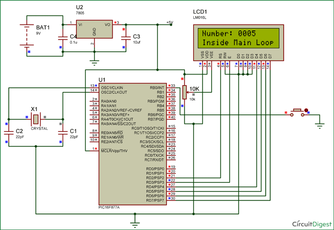
The circuit diagram for using PIC16F877 interrupts is given in the above image. You simply have to connect the LCD to the PIC as we did in interfacing LCD tutorial.
Now to connect the interrupt pin, we should look at the datasheet to know which pin of the PIC is used for External interrupt. In our case in PIC16F877A the 33rd pin RBO/INT is used for external interrupt. You cannot use any other pin other than this pin. The Pin connection for this circuit diagram is shown in the table below.
|
S.No: |
Pin Number |
Pin Name |
Connected to |
|
1 |
21 |
RD2 |
RS of LCD |
|
2 |
22 |
RD3 |
E of LCD |
|
3 |
27 |
RD4 |
D4 of LCD |
|
4 |
28 |
RD5 |
D5 of LCD |
|
5 |
29 |
RD6 |
D6 of LCD |
|
6 |
30 |
RD7 |
D7 of LCD |
|
7 |
33 |
RBO/INT |
Push button |
We have enabled internal pull up resistors on PORT B, hence we can directly connect the RB0 pin to ground via a Push button. So whenever this pin gets LOW an interrupt will be triggered.
The connections can be made on a Bread board as shown below.
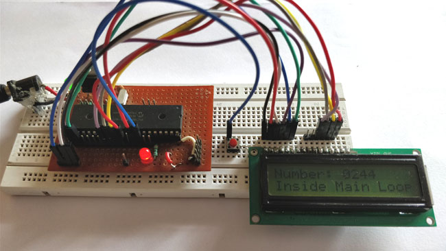
If you have been following our tutorials you should have got familiar with this Perf Board that I have used here. If not, you need not think much about it just simply follow the circuit diagram and you will get things working.
Simulation of Interrupts in PIC Microcontroller:
The Simulation for this project is made using Proteus.
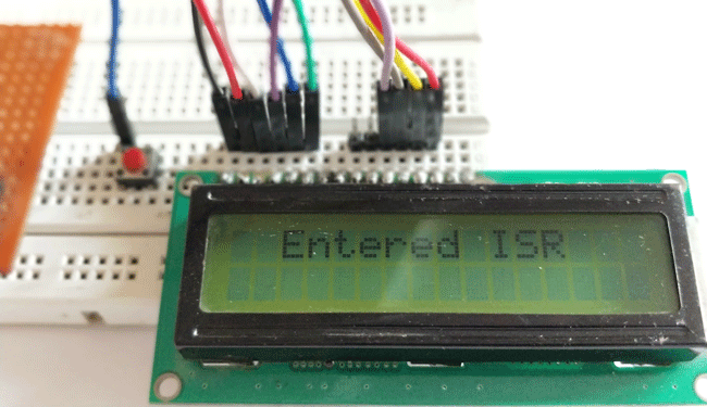
When you simulate the project you should see a sequence of numbers being incremented on the LCD display. This happens inside the main loop and whenever the push button is pressed the LCD should display that it has entered into ISR. You can make your modifications in the code and try testing it here.
Code Explanation:
The complete code for this project can be found at the end of this tutorial. However the program is split into important chunks and explained below for your better understanding.
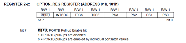
Like all programs we have to begin the code by defining the pin configuration for the pins that we use in our program. Also here we need to define that we are using RB0/INT as an external interrupt pin and not as a input or output pin. The below line of code enables the internal pull-up resistor on portB by making the 7th bit as 0.
OPTION_REG = 0b00000000;
Then we enable the Global/Peripheral interrupts and declare that we are using RB0 as an external interrupt pin.
   GIE=1;          //Enable Global Interrupt

    PEIE=1;         //Enable the Peripheral Interrupt

    INTE = 1;       //Enable RB0 as external Interrupt pin
Once the RB0 pin is defined as an external interrupt pin, each time it gets low the external interrupt flag INTF will become 1 and the code inside the void interrupt function will get executed since the Interrupt Service Routine(ISR) will be called.
void interrupt ISR_example()

{

        if (INTF==1) //External Interrupt detected

        {

            Lcd_Clear();

            Lcd_Set_Cursor(1,1);

            Lcd_Print_String("  Entered ISR");

           INTF = 0;          // clear the interrupt flag after done with it

           __delay_ms(2000);

            Lcd_Clear();

        }

}
As you can see I have named the interrupt function as ISR_example. You can name it as per your wish. Inside the interrupt function we will check if the INTF flag is high and perform the needed actions. It is very important to clear the interrupt flag once you are done with the routine. Only then the program will return back to void main function. This clearing has to be done by software using the line
INTF = 0; // clear the interrupt flag after done with it
Inside the main function, we just increment a number for every 500 ms and display it on the LCD screen. We do not have any specific line to check the status of the RB0 pin. The interrupt will always stay active and whenever the push button is pressed it will jump out of void main and execute the lines in the ISR.
    Lcd_Set_Cursor(2,1);

        Lcd_Print_String("Inside Main Loop");

        Lcd_Set_Cursor(1,1);

        Lcd_Print_String("Number: ");

        Lcd_Print_Char(ch1+'0');

        Lcd_Print_Char(ch2+'0');

        Lcd_Print_Char(ch3+'0');

        Lcd_Print_Char(ch4+'0');


        __delay_ms(500);

        number++;
Working of PIC16F877A Interrupts:
Once you have understood how the interrupt works you can try it out on the hardware and fiddle around it. This program given here is a very basic example of external interrupt where it just changes the display of the LCD screen when an interrupt is detect.
The complete working of the project can be found in the video given below.Hope you understood about interrupts and where/how to use them. If you have any doubts you can reach me through the forums or through the comment section.
Complete Project Code
#define _XTAL_FREQ 20000000
#define RS RD2
#define EN RD3
#define D4 RD4
#define D5 RD5
#define D6 RD6
#define D7 RD7

#include <xc.h>

#pragma config FOSC = HS        // Oscillator Selection bits (HS oscillator)
#pragma config WDTE = OFF       // Watchdog Timer Enable bit (WDT disabled)
#pragma config PWRTE = ON       // Power-up Timer Enable bit (PWRT enabled)
#pragma config BOREN = ON       // Brown-out Reset Enable bit (BOR enabled)
#pragma config LVP = OFF        // Low-Voltage (Single-Supply) In-Circuit Serial Programming Enable bit (RB3 is digital I/O, HV on MCLR must be used for programming)
#pragma config CPD = OFF        // Data EEPROM Memory Code Protection bit (Data EEPROM code protection off)
#pragma config WRT = OFF        // Flash Program Memory Write Enable bits (Write protection off; all program memory may be written to by EECON control)
#pragma config CP = OFF         // Flash Program Memory Code Protection bit (Code protection off)


//LCD Functions Developed by Circuit Digest.
void Lcd_SetBit(char data_bit) //Based on the Hex value Set the Bits of the Data Lines
{
if(data_bit& 1)
D4 = 1;
else
D4 = 0;

if(data_bit& 2)
D5 = 1;
else
D5 = 0;

if(data_bit& 4)
D6 = 1;
else
D6 = 0;

if(data_bit& 8)
D7 = 1;
else
D7 = 0;
}

void Lcd_Cmd(char a)
{
RS = 0;
Lcd_SetBit(a); //Incoming Hex value
EN  = 1;
        __delay_ms(4);
        EN  = 0;
}

void Lcd_Clear()
{
Lcd_Cmd(0); //Clear the LCD
Lcd_Cmd(1); //Move the curser to first position
}

void Lcd_Set_Cursor(char a, char b)
{
char temp,z,y;
if(a== 1)
{
 temp = 0x80 + b - 1; //80H is used to move the curser
z = temp>>4; //Lower 8-bits
y = temp & 0x0F; //Upper 8-bits
Lcd_Cmd(z); //Set Row
Lcd_Cmd(y); //Set Column
}
else if(a== 2)
{
temp = 0xC0 + b - 1;
z = temp>>4; //Lower 8-bits
y = temp & 0x0F; //Upper 8-bits
Lcd_Cmd(z); //Set Row
Lcd_Cmd(y); //Set Column
}
}

void Lcd_Start()
{
  Lcd_SetBit(0x00);
  for(int i=1065244; i<=0; i--)  NOP();
  Lcd_Cmd(0x03);
__delay_ms(5);
  Lcd_Cmd(0x03);
__delay_ms(11);
  Lcd_Cmd(0x03);
  Lcd_Cmd(0x02); //02H is used for Return home -> Clears the RAM and initializes the LCD
  Lcd_Cmd(0x02); //02H is used for Return home -> Clears the RAM and initializes the LCD
  Lcd_Cmd(0x08); //Select Row 1
  Lcd_Cmd(0x00); //Clear Row 1 Display
  Lcd_Cmd(0x0C); //Select Row 2
  Lcd_Cmd(0x00); //Clear Row 2 Display
  Lcd_Cmd(0x06);
}

void Lcd_Print_Char(char data)  //Send 8-bits through 4-bit mode
{
   char Lower_Nibble,Upper_Nibble;
   Lower_Nibble = data&0x0F;
   Upper_Nibble = data&0xF0;
   RS = 1;             // => RS = 1
   Lcd_SetBit(Upper_Nibble>>4);             //Send upper half by shifting by 4
   EN = 1;
   for(int i=2130483; i<=0; i--)  NOP();
   EN = 0;
   Lcd_SetBit(Lower_Nibble); //Send Lower half
   EN = 1;
   for(int i=2130483; i<=0; i--)  NOP();
   EN = 0;
}

void Lcd_Print_String(char *a)
{
int i;
for(i=0;a[i]!='\0';i++)
  Lcd_Print_Char(a[i]);  //Split the string using pointers and call the Char function
}
/*****End of LCD Functions*****/


/****Interrupt function ****/
void interrupt ISR_example()
{
        if (INTF==1) //External Interrupt detected
        {
            Lcd_Clear();
            Lcd_Set_Cursor(1,1);
            Lcd_Print_String("  Entered ISR");
           INTF = 0;          // clear the interrupt flag after done with it
           __delay_ms(2000);
            Lcd_Clear();
        }
}
/****End of Interrupt Function****/

int number =0;
char ch1,ch2,ch3,ch4;
int main()
{
    TRISD = 0x00; //PORTD declared as output for interfacing LCD
    TRISB0 = 1;        //DEfine the RB0 pin as input to use as interrupt pin
    OPTION_REG = 0b00000000;  // Enables PULL UPs
    GIE=1;          //Enable Global Interrupt
    PEIE=1;         //Enable the Peripheral Interrupt
    INTE = 1;       //Enable RB0 as external Interrupt pin
    Lcd_Start();

    while(1)
    {
        ch1 = (number/1000)%10;
        ch2 = (number/100)%10;
        ch3 = (number/10)%10;
        ch4 = (number/1)%10;

        Lcd_Set_Cursor(2,1);
        Lcd_Print_String("Inside Main Loop");
        Lcd_Set_Cursor(1,1);
        Lcd_Print_String("Number: ");
        Lcd_Print_Char(ch1+'0');
        Lcd_Print_Char(ch2+'0');
        Lcd_Print_Char(ch3+'0');
        Lcd_Print_Char(ch4+'0');

        __delay_ms(500);
        number++;

    }
    return 0;
}
Comments
Hi Abel,
While displaying on LCD we should add a NULL '0" to the generated character due to the following reason.
LCD's can display only characters and strings. But here the variables ch1, ch2, ch3 and ch4 contains data which are in decimal format. So if your variable ch1 has a value of 33 and you try printing it by using the below line.
Lcd_Print_Char (ch1);
You will find the number "!" (Exclamatory sign) being printed on the LCD screen. This is because the char value for number 33 is "!".
You should take a look at the ASCII chart to know the char value of decimal numbers. For zero the char value is 48, so you can either add 48 to the decimal number or add '0' (Char zero value is 48) to solve this problem.
This is a common practice that is followed for all MCU to display decimal characters to any display modules
Hope this answers your question. And thanks for your words
i want to understand the complete process of interrupt control registers and how do they work and how we are using them in it. circuit digest i watched your video on youtube but there you explained its working. i know how it is working and what will happen when an interrupt comes. only the problem comes with interrupt control register section
CAN i USE I2C AND TIMER 0 AT THE SAME TIME?? IS FOR INTEGRATING A PROGRAM THANKS
hi sir,
i wants know about adc interrupt program. already try this but did not get out put.kindly clear my doubt......my code is given below.......
#include<htc.h>
#define lcd PORTD
#define en RE0
#define rw RE1
#define rs RE2
#define __XTAL__FREQ 4000000
unsigned int adressl,adressh,adctotal,flag=0;
void delay(unsigned char a)
{
while(a--);
}
void data(unsigned char a)
{
rs=1;
rw=0;
delay(1500);
lcd=a&0xf0;
en=1;
delay(1500);
en=0;
delay(1500);
lcd=(a<<4)&0xf0;
en=1;
delay(1500);
en=0;
delay(1500);
}
void command(unsigned char a)
{
rs=0;
rw=0;
delay(1500);
lcd=a&0xf0;
en=1;
delay(1500);
en=0;
delay(1500);
lcd=(a<<4)&0xf0;
en=1;
delay(1500);
en=0;
delay(1500);
}
void adc()
{
int c,d,b,a;
adctotal=(ADRESH*256)+ADRESL;
a=adctotal/2.05;
d=a/100;
c=(a%100)/10;
b=(a%100)%10;
data(d+0x30);
data(c+0x30);
data(b+0x30);
}
void ini()
{
command(0x02);
command(0x28);
command(0x0e);
command(0x06);
command(0x80);
}
void string(unsigned char *p)
{
while(*p)
{
data(*p++);
}
}
void interrupt anolog()
{
if(ADIF==0);
adc();
ADIF=0;
}
void main()
{
ADIF=0;
ADIE=1;
PEIE=1;
GIE=1;
ADCON0=0XC5;
ADCON1=0XC2;
PORTB=0X00;
TRISB=0X01;
PORTA=0X00;
TRISA=0X01;
PORTD=0X00;
TRISD=0X00;
PORTE=0X00;
TRISE=0X00;
ini();
string("Temprature:");
}
How can 3 pushbutton conect to port D on pic16f877A by using interruption for controlling 3leds
Sadly PIC16F877A does not have 3 external interrupts. So the best way to do it is use three digital pins for three pushbutton and combine the output of all thee button to the external INT pin. So when ever the button is pressed you can jump into the ISR and use the digital I/O pin to detect which particular button was pressed.
HI ,
IF POSSIBLE please provide I2C basics for 16F877A and how to interface with EEPROM AND RTC
ITS HELPFUL TO SELF LEARNING .
THANKS & REGARDS
BOOBALAN
#define START 0
#define STOP 1
#define RESTART 2
#define WAIT 3
#define ACK 4
#define NOACK 5
void rtc_init();
void rtc_process(unsigned char);
void rtc_send(unsigned char);
unsigned char rtc_receive();
void rtc_write(unsigned char,unsigned char);
unsigned char rtc_read(unsigned char);
void rtc_init()
{
TRISC |= 0x18;
SSPSTAT = 0x80;
SSPCON = 0x28;
SSPADD = 20000000/((100000*4)-1);
}
void rtc_process(unsigned char x)
{
switch(x)
{
case(0): SEN=1; while(SEN); break;
case(1): PEN=1; while(PEN); break;
case(2): RSEN=1; while(RSEN); break;
case(3): while((SSPSTAT & 0x04) || (SSPCON2 & 0x1F)); break;
case(4): ACKDT = 0; ACKEN = 1; while(ACKEN); break;
case(5): ACKDT = 1; ACKEN = 1; while(ACKEN); break;
default: break;
}
}
void rtc_send(unsigned char x)
{
rtc_process(WAIT);
SSPBUF = x;
while(BF && !SSPIF);
SSPIF = 0;
rtc_process(ACK);
rtc_process(WAIT);
}
unsigned char rtc_receive()
{
unsigned char x;
rtc_process(WAIT);
RCEN = 1;
while(!BF);
x = SSPBUF;
rtc_process(NOACK);
rtc_process(WAIT);
return(x);
}
void rtc_write(unsigned char x,unsigned char y)
{
rtc_process(START);
rtc_send(0xD0);
rtc_send(x);
rtc_send(y);
rtc_process(STOP);
}
unsigned char rtc_read(unsigned char x)
{
unsigned char dat;
rtc_process(START);
rtc_send(0xD0);
rtc_send(x);
rtc_process(RESTART);
rtc_send(0xD1);
dat = rtc_receive();
rtc_process(STOP);
return(dat);
}
//Use this file as header file
rtc_write(0x00,0x03); //sec register 0x00 value 0x03
char m = rtc_read(0x00); //read sec
Hello there buddy, nice piece of work, Im studying by myself how external interrupts works so i found your site, very complete, to understand more the concept i wanted to run your program and i did, its running, using even the LCD, but when i try to call the ISR nothing happens, any idea ?
Are you using the same program? If you have edited the program use the simulator to check if things are working properly. If it works on simulation, then it is most probably with circuit connection. Make sure the interrupt reaches the hardware pin use a multimeter to check fo voltage levels
how to write code capture timer interrupt

what a good tutorial i love this explanation... my question is why adding null('0') to ch1,ch2,ch3and ch4? why not assign directly??