
Water tank overflow is a common problem which leads to the wastage of water. Though there are many solutions like ball valves which automatically stop water flow once the tank gets full, electronics enthusiasts prefer smart electronic solutions. This comprehensive water level indicator project tutorial will guide you to build a simple DIY water level indicator circuit that detects water levels and raises an alarm when your tank reaches preset levels - perfect for preventing overflow and water wastage.
This simple transistor based water level indicator circuit is very useful to indicate the water levels in a tank. Whenever tank gets filled, we get alerts on particular levels. Here we have created 4 levels (low, medium, high and full), we can create alarms for more levels. We have added 3 LEDs to indicate initial three levels (A, B, C), and one Buzzer to indicate FULL level (D). When tanks gets filled completely we get beep sound from Buzzer. If you want to improve the project by adding a display and automatic motor on-off control then you can simply add a microcontroller like Arduino to sense the water changes and control the display and motor accordingly, if you want more details about that project you can check out the Arduino based water level indicator and controller project.
Updated: This article was last updated in June 2025 with purchase links, troubleshooting tips, and FAQ section.
Components Required for Water Level Indicator Circuit
- 4 - BC547 transistors
- 6 - 220 ohm resistors
- 3 - Colour LEDs - red, green, and yellow
- 1 – Buzzer
- 5 - 9v battery + battery clip
- Breadboard
Water Level Indicator Circuit Diagram
This transistor-based water level indicator circuit is highly effective for monitoring water levels in tanks and containers. The water level sensor circuit provides alerts at four different levels (low, medium, high, and full) using visual and audio indicators. This makes it an ideal water tank alarm system for residential and commercial applications.
The complete circuit diagram for the water overflow alarm project can be found below. As you can see the circuit is simple and easy to build as it only has few basic components like transistors, resistors, LEDs and a buzzer

We can consider this whole circuit as 4 small circuits, each one for indicating/alarming, when a particular level (A,B,C,D) of water have been reached.
When water level reaches to point A, circuit with RED LED & transistor Q1 gets completed and RED LED glows. Similarly when water level reaches to point B, circuit with YELLOW LED and transistor Q2 gets completed and Yellow LED glows, same goes with point C. And finally when tank gets full (Point D), circuit with buzzer gets completed and buzzer starts beeping.
Low Water Level Alarm Circuit - Working
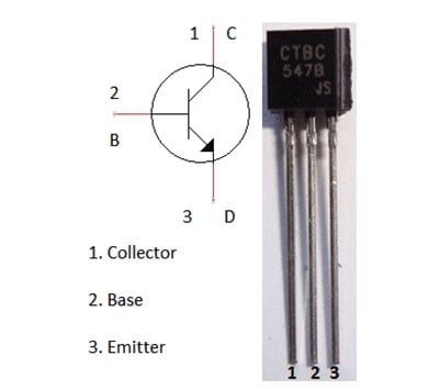
Here we are using NPN transistor as a Switch. Initially there is no voltage applied to the base of the Transistor Q1 and the transistor is in OFF state and no current is flowing through collector and emitter and LED is OFF (See below diagram to understand Transistor Pin structure).
When the water level reaches to Point A in the tank, the positive side of the battery gets connected to the base of the Transistor Q1 through the water. So when a positive voltage has been applied to the base of the Transistor Q1, it gets into ON state and current starts flowing from collector to emitter. And RED LED glows.
You can see resistors (R1, R2, R3) at the base of each transistor, which is used to limit the maximum Base current. Generally a transistor gets its ON state fully when a voltage of 0.7 V is applied to the base. There are also resistors (R4, R5, R6) with each of the LEDs, to drop the voltage across LEDs, otherwise LED may blow up.
Same phenomenon happens when water level reaches to Point B. As soon as water level reaches to Point B, a positive voltage gets applied to the Transistor Q2, it gets ON and current started flowing through YELLOW LED, and LED glows. With same principle, GREEN LED glow when water level reaches to Point C.And finally Buzzer beeps when water level reaches to D.
Note that Left most wire in the tank must be lengthier than other four wires in the tanks, because this is the wire which is connected to positive voltage.
The complete working of the water level indicator project can be found in the video linked to the bottom of this page.
Applications of Water Level Indicator
This water level indicator project has numerous practical applications in daily life and industrial settings:
- Overhead water tank monitoring in homes and buildings
- Swimming pool water level management
- Industrial tank monitoring systems
- Agricultural irrigation tank control
- Sump pump water level detection
- Aquarium and fish tank water management
Troubleshooting Water Level Indicator Circuit
If your water level indicator circuit is not working properly, check these common issues:
- LEDs not glowing: Check battery connections and ensure 9V battery has sufficient charge
- False triggering: Clean your connections make sure the base of the transistors are connected correctly.
- Buzzer not working: Verify buzzer connections and test if you have an active buzzer or passive buzzer
- Intermittent operation: Check breadboard connections and ensure proper wire contact

Frequently Asked Questions
How does a water level indicator work?
The water level indicator works by using water as a conductor to complete electrical circuits at different levels, triggering LEDs and buzzers as indicators.
What is the cost of making this water level indicator project?
The total cost is approximately $10-15, making it an affordable DIY electronics project for students and hobbyists.
Can this circuit work with AC mains supply?
No, this circuit is designed for 9V DC supply only. For AC mains operation, additional safety circuits and transformers are required.
Is this water level indicator safe to use?
Yes, this circuit operates on low voltage (9V DC), making it completely safe for home use and for students to learn and experiment. The current through water is minimal and poses no safety risk.
Conclusion
Hope you understood the tutorial and enjoyed building your own water level indicator circuit. If you are still having any questions trouble, you can leave them in the comment section below or use the "Ask our community" option at the bottom of this page to get in touch with us and engage with our other community members.
Related Projects
If you are interested in building similar electronics projects, you can check out our other tutorials that we have built here at CircuitDigest. Like always, the complete step-by-step instructions with downloadable code and circuit diagram can be found for all tutorials below so that you can easily build them on your own.
- Arduino Water Level Indicator and Controller - Advanced version with automatic pump control and LCD display
- Water Level Sensor with Arduino Tutorial - Learn how industrial water level sensors work with microcontrollers
- Automatic Wireless Water Pump Controller - RF-based wireless pump control system using logic gates
- ESP8266 Wireless Water Level Controller - IoT-enabled water conservation system
- Contactless Liquid Level Sensor Project - Capacitive sensor for non-contact water detection
- Water Flow Sensor with Arduino - Monitor water flow rate and volume measurement
- Rain Detector Alarm Circuit - A Similar transistor-based circuit for rain detection
- Simple Soil Moisture Detector Circuit - Transistor-based moisture sensing for plants
- Automatic Water Dispenser using Arduino - Ultrasonic sensor-based contactless water dispenser
Comments
yes it will works on large tank also
Yeahh it will definitely work for large tank yashh
Hi sir please send the Water level indicator using transistor
its a demo project...if u will make a large base project then it will work....bt d concept z same...
Of course, it will work, but you need a proper installation.
can a (BC547 or BC548) transistor be used instead of the BC507 transistor
We are already using BC547 transistor, any General Purpose small signal NPN transistor should work here.
ya you can use ....or any other general purpose transistors also
Sir may I use it in my 1500L tank .. Will it woperfectly ? And me fast sir.
As previously stated, it will definitively work in any tank but you need a proper installation, concept will remain the same.
Sir, why not you have used resistor with the transister connected with the buzzer?
Yes, you can also use current limiting Resistor for the forth Transistor, to prevent it from any kind of damage.
Sir, will it work with long wires like from terrace to room
yes
Yes
yes priyanka its working
before I complete the device and then I m using the device
Sir pls help ..
I have arranged all rrquired components according to the given circuit bt the circuit gets completed at the transistor level nd the led strts glowing as i connect the battery to the circuit without placing those other ends in water .. Help me sir ..
hi same thing happening with me too. I made 2 circuits and 1 led glowed when i connected with the battery and with the 2nd circuit the buzzer is buzzing without pouring water. The circuit looks right but idk what the problem is? Can you help please. Thanks
Sir
I am making your project but sir me use transistor bc548 so sir any problem
Please rply
its super
i want to attach buzzer on each LED then what should i do, please guid...
thx
Sir
How long is the maximum distance in meters form a 5 volts or 9 volts battery ? Like with an UTP network cable.
Dear Sir,
My query is that I want to install the system at ground floor and put the wires in the water tank located on second floor. For that I have to pull the wires for approximately 40 feet . So for such a long length wouldn't there be copper losses and would it function with 9V battery
The voltage drop is dependent upon the resistance of wire, load resistance and current through the wire. But roughly according to this circuit, we can use it upto 100-150 feets. You can check some online voltage drop calculators to find the accurate length according to your wire.
Sir as on 28 Feb we are celebrating science day I am going to exhibit this model but sir.... Asci have tested once I observed that the Buzzer will not scream loudly as it just sounds in small amount only like a whistle. so myvdoubt is ... Is this buzzer will be able to warn the person.... Plz reply
You can either use some Alarm with external power supply and transistor as a trigger or You can use AC alarm with a Relay in place of Buzzer. Check How to use Relay here.
Hi, I have made this water level indicator but it is not working properly because the water is not connecting the wires inside it. However when I put salt in the water it works. If possible help me in this issue.
Probably you are using Purified Water or Distilled Water, which does not conduct electricity. And after adding salt (ionized substances), it becomes conductor.
what is the limitation of this project?
sir, i have completed this project on pcb board with proper designing of pcb.but the problem is that not even a single LED is glowing.can you please suggest where may be the fault??
and sir i have connected the base of the transistor to the sensor,emitter to -ve termonal of battery and collector to LED.Is it right,sir??
This is a very simple circuit and should work without any issue, have you connected LED terminals properly according to polarity.
Can I connect a motor instead of led or buzzer??
Once water reaches certain level , motor should start??
Sir,
Can I use motor by replacing the buzzer ??
Is any possibilities here when the water will have reached the top of the tank then the motor will off??
I mean the pump motor which is using to enlarge the water level of the tank!!
Can I use motor by replacing the buzzer ??
@Hasan and @Sunny Yes you can use Pump motor. A Relay will be used for this. To switch Off the motor, use Relay with PNP transistor and to switch On the motor use Relay with NPN transistor. Check this for Relay connections.
Shall I use 12 v battery instead of 9 v
Why do we need the transistor, i know that it works as a switch here, but what happens if i directly connect the led cathode to the wire and drop it into the water instead of connecting the transistor? Theoretically it will work, but what happens if I implement it practically?
Water is not a perfect conductor, but it can conduct enough to trigger Transistors to Glow LEDs. Hence Transistor is also used here as Amplifiers.
You can do this by increasing current of supply by using mobile charger or else and check with multimeter to find excess voltage to use appropriate resistor.
I have made such a working circuit and using it in perfect working condition.
Most mobile chargers are small SMPS devices that reduce the mains voltage to 5.1v etc etc, and usually there is no isolation of the mains from the output, so one runs the risk of electrocution if a mobile charger is used to run the device so a mobile charger would not be a good idea to power the device. Use a 9v battery or a power supply using s step down transformer... the battery eliminator kind of thing.
conductivity of water is less compared to conductor.power loss is acquired in water so it not enough for gloving led.we are using trasister required 0.7v input for switching transister.
Sir ,What happens if we change the resistor values?? And can i replace the buzzer with an 8 ohm speaker.if yes shall i need to connect resistor at fouth trasistor also??
You can use Speaker with some musical IC, check this circuit Siren Generator Circuit. And search more circuits on Speaker on this site.
Hi, I have made this water level indicator but it is not working properly because the water is not conducting elecyricity. If possible help me in this issue.
Can i used bc-548 transistor?
Nd can i used 470 ohm registor insteand of 230ohm registor?
@Joe: Check above comments for Water conductivity problem.
@neel: Yes you can use BC548 and 470 Ohm resistor
may i use transformer instead of 9v battery?
Instead of long wire, I want the circuit for wire less.please
May I get single led glow at particular level.if possible can you suggest me sir.as I am facing difficulty with that.
Dear,
The buzzer will produce a steady sound. Instead of that, if I need to sound like a siren, then how I can achieve this. I assume some capacitor/resistor may solve the problem. But I don't know how to connect those components to the base of the transistor.
Dear - How to make the buzzer sound like a siren instead of just producing a steady sound?
Check this circuit: Melody or Sound Generator Circuit
Can I increase the no of LED indicators to 7 by repeating the Transistor circuit 4 more times?
hello
i made the circuit according to above shown figure but i connect mobile charger as a source in place of 9v battery all LEDs works fine but there is problem with buzzer there is no sound from it when i complete circuit by dropping wires in water tank but it works fine if i connect wire directly..
Sir
How can use this circuit reverse type. Because i wan't measure water level in my water well. Actually I want low level indicator. Water level is gone down i want indicate the led. How can use this. Pls help me.
Use PNP transistor BC557 in place of BC547 and reverse the order of LED/buzzer.
What is the least Price for this indicator??
Thanks sir.
sir which type of transistor we are using in this project i mean pnp or npn???
sir can we make this circuitju without transustor and resistor...
sir,how much money to be used for this project?
The circuit is complete when voltage flows through the water.. But if the voltage flows, then the current may also flow. So, if I use it for my houses tank, would current flowing in the water be a problem, or the water does not get electrocuted, please do give me a quick and sufficient answer.
Thanks.
Yes current will flow through the water, but current from 9v battery is not harmful.
Hear after I try this
Thank you for the briefing man! but is it necessary to use a battery? is there any change that would happen if i apply a bridge rectifier circuit instead of battery? if yes, do i have to change the resistor value if the output of rectifier is 12v?? thanks man.
Sir.. I complete the ckt. Of water level indicator bt one doubt is that if my tank is full then buzzer will start bt till the level of water is full the buzer will operate on for long time so how i can stop to this
Dear sir,
How we convert 5-9 V into 220/230V ??
Please tell me...
respected sir
can i use transformer in place of 9 V battery and motor as buzzer
if yes
what will be connection
@kaushik @bobby: yes you can, check our Cell Phone Charger Circuit
For how long will the buzzer sound? I mean, once you are alerted, how can you stop the sound of buzzer? turning the circuit off wouldn't be a good idea as it would be in efficient to turn the circuit on and off again.
the buzzer used in this ckt is having very low sound . i want to increase the strength of the buzzer or use some other device for that purpose. what is the solution for dat?
Trigger some 220/110V AC alarm with the help of Relay and be careful while working with 220v, it can be lethal.
i need help on this very topic of the project.
will i give home voltage to it
why not we use PNP instead of NPN. let suppose we use PNP what will be the impact on the circuit.
Super idea sir...But I have to implement using wireless technique sir..I have an Arduino board..Give me an idea sir
Check this one: Automatic Water Level Indicator and Controller using Arduino
Sir, the circuit is working properly on 9v battery.but I have used a 9v transformer here and seven colors led .the problem is that,I am getting the output but the led's a are not blinking and the buzzer is not making proper sound.
Please help.
You first need to have proper 9v regulated power supply from the Transformer, you cant just directly connect the Transformer. Check this circuit: Cell Phone Charger Circuit
If we add a diode in the forward biased direction anywhere in the circuit, will it change the outcome?
Transistor burn when prob short please give the solution of prob short transistor not burn.
Thanks
shiv singh
Can anyone tell me how to use buzzer at low level to indicate empty tank?

Will this work in a large water tank?